This thread has been locked.
If you have a related question, please click the "Ask a related question" button in the top right corner. The newly created question will be automatically linked to this question.
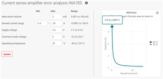
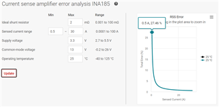
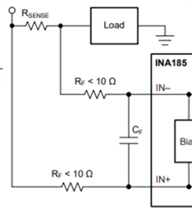
HelloWe are using the following TI parts for our application.1) INA185A2IDRLT2) ADS1118IDGSR3) TMUX1108PWR4) TMUX1104DGSR5) TXB0108PWRWe design this circuit for a precision current monitoring application.Our current range is from 0.5A to 30A.Using this design how much accuracy we can expect, can we simulate this design to check the accuracy.Please review this SCH and give us your valuable feedback.Thanks and Regards,Hrishikesh Kamble
Hrishikesh,
Thanks for the question and using the E2E forum.
The accuracy you can expect from the INA185 will depend on two additional factors. What is the expected common-mode voltage, and what will be the operating temperature? The product folder has a great tool that will show you how much error you can expect based on your specific conditions here.
Because I don't know what the Vcm and temperature are, I ran the analysis for you with three different Vcm values (0, 13, and 26), all at 25C. You can see that the higher the Vcm gets, the greater the error, especially on the low end of the sensed current. The best-case scenario is when Vcm = 0, and in that condition, the worst-case accuracy is at 0.5A (in this case the error is ~7%). Your highest error will always come at the lowest current due to errors such as Ib and output swing.
Please let us know if you have any additional questions.
Louis
Hello Louis,
Thanks for your reply.
we are using this design in low side configuration so VCM shall be negligible correct?
Also please review the SCH and let me know if you observed any issue in hole design.
Thanks & Regards,
Hrishikesh Kamble.
Hrishikesh,
Yes, if the device is being used on the low-side, your error will be less than at a higher Vcm (13V for example).
I don't see any issues with the INA devices in the schematic, and it doesn't look like they connect to anything else in the schematic except for LUGxx somewhere else in the circuit, and Vout to the MUXs. The only additional suggestion I might make is to put 0ohm resistors and a DNP capacitor footprint on the inputs for a potential future input filter should the need arise.
However, I don't have enough experience with the other devices to provide proper feedback. I suggest you reach out to the other teams responsible for those devices to seek out their opinions.
Please let us know if you have any further questions.
Louis