


Part Number: LMH6574
Other Parts Discussed in Thread: TL074, OPA4872
Hello Ti Engineers!
I have run across a strange issue with the 6574. To verify the issue I built a test jig in which I give the 6574 just 2 inputs. The IC is powered by +/-5V, and I tried loading with 100 and 56R. Feedback resistor is 2.2k (unity gain).
(a) DC from 0-1V
(b) A ramp waveform (actually from the horizontal section of an oscilloscope)
The issue is that waveform (b) is not being faithfully transferred to the output. It's levels seem to be slightly dependent on the level of the DC voltage previously presented on the other input! The effect is noticeable on looking at the top or bottom of the ramp.
The following scope images capture this point.(I am trying to figure out how to link to a full-res image, but I'll post anyway.)
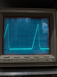
This is the ramp waveform fed to Pin 3 (IN1). Timebase is 0.2us/div, Vertical is 0.2V/div.
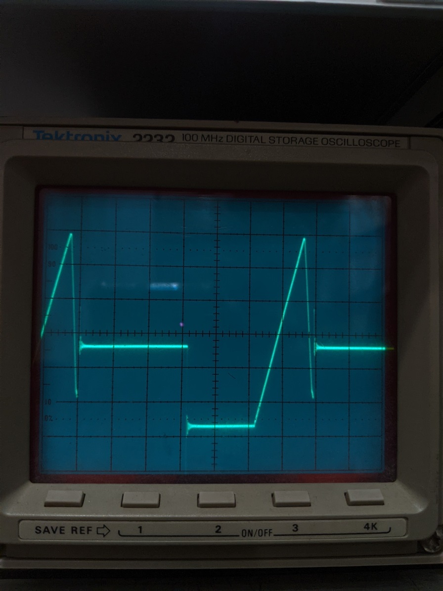
The next two images show the ramp at the output of the 6574
This image shows the output when PIn 7 (IN3) is held at 0V:
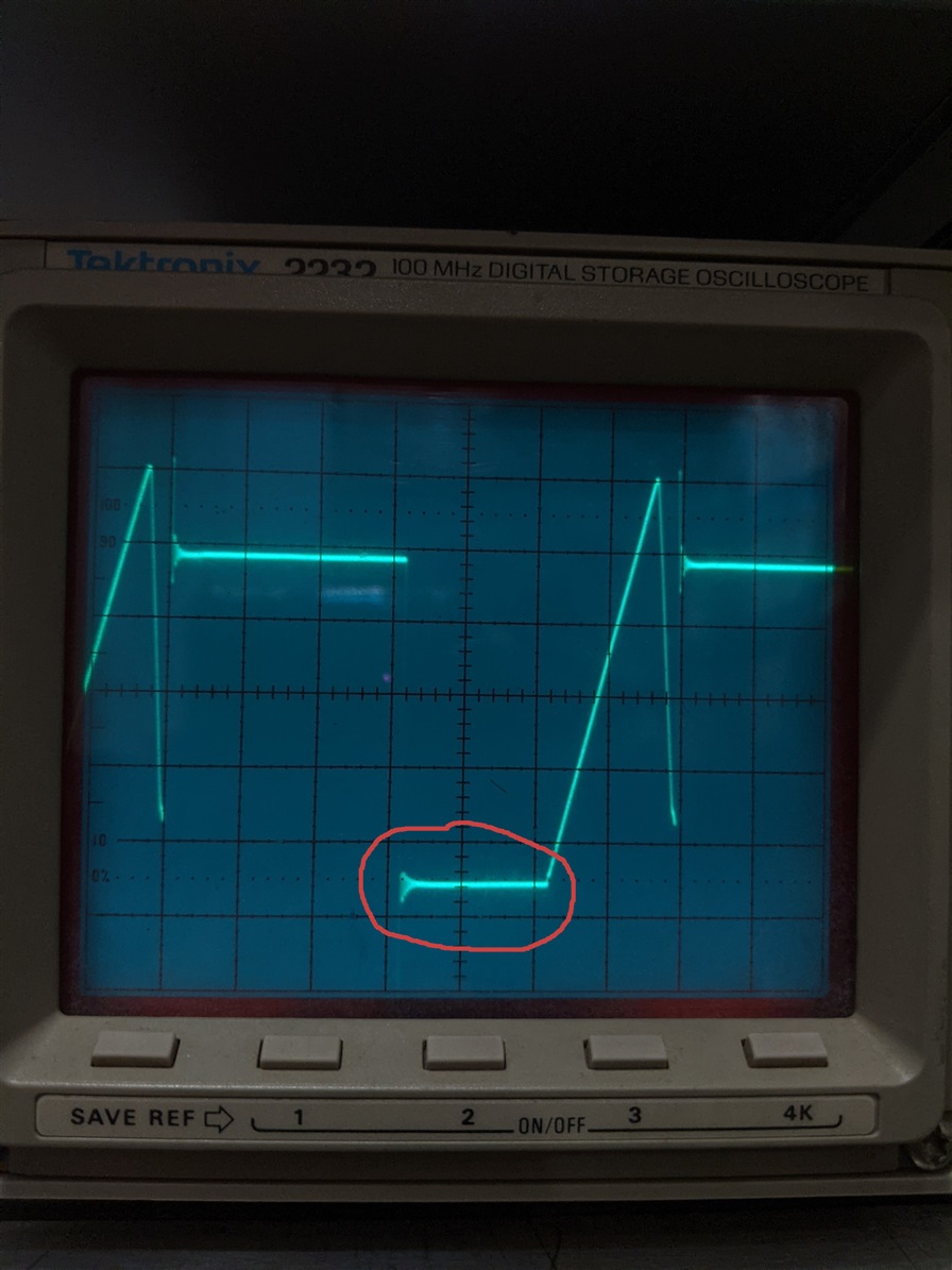
And this image shows the same output when Pin 7 is raised to about 0.5VDC. What has happened here is that compared to the previous image, the ramp has moved up by almost a minor division. The circled section at the bottom of the ramp shows the effect (also noticeable at the top peak). The effect can be seen very clearly clearly if I vary the DC input continuously from 0-1V using a pot; the indicated horizontal segment also moves slightly up and down. It is almost as if the IC remembers what input voltage was present at IN3!
What is even more curious is that if I turn off the channel switching and keep Pin 13 low, so as to exhibit only the ramp, then varying the DC at IN3 has no effect - appropriately enough. The signal at IN3 seems to "leak through" only while channel switching is taking place.
Any suggestions on what could be causing this would be greatly appreciated!
TIA - Ram

