This thread has been locked.

If you have a related question, please click the "Ask a related question" button in the top right corner. The newly created question will be automatically linked to this question.

INA826: current sense schematic review

Part Number: INA826

Hi,

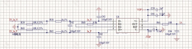
I'm using INA826 to do current sensing, the current flows from IN_Ic_P to IN_Ic_N, the schematic is as below, ±5V supply for the device.

Could you please help review the schematic?

  • Hi Justifice,

    should work.

    It is a bit unusual that the shunt is splitted into two equal parts with ground connected to the midpoint. Is there any special reason for it?

    Kai

  • Hi Justifice,

    Thanks for your post, I can help you. In addition to Kai's question, what is the input current range? I want to make sure the voltages developed at the input of the INA are within linear range. 

  • the midpoint connected to GND is to make sure that the common mode input voltage is 0.

  • Hi Justifice,

    Per your INA826's configuration, here is Vcm and Vout linear relationship is going to be.

    The differential input voltage for INA826 is from -592.883mV to 586.833mV, which I duplicated your power rails, gain settings and Vcm settings.  

    If you are interested the above took, please download it from the link below. 

    https://www.ti.com/tool/ANALOG-ENGINEER-CALC

    You mentioned that this is a current sensing application. Since I do not know your current sensing range, I placed 100mΩ Rsense resistor as shunt for the measurement. With R_shunt = 100mΩ, the circuit is able to sense approx. +/- 586/100 = +/- 5.86A as shown in the simulation below.


    INA826 E2E 01162022.TSC

    It is not clear what are two 10Ω resistor in series connected to a mid ground is for. If you want to keep Vcm input voltage near ground, the above circuit is able to accomplish that if the sensing current is small. INA826 is only interested the differential input voltages across the shunt resistor per the current sensing application.  

    If 10Ω shunt is used for the sensing resistor, then the sensing current in the circuit is only approx. +/- 586mV/10Ω  = +/- 58.6mA, which my guess is not what you want. I am not sure what you are trying to do, If both 10Ω resistors are indeed sensing resistors, please draw out the analog front end of the current sensing circuit. You may also simulate the configuration by modifying the above circuit as well.  

    Regarding to the differential and the common mode LPF configuration, the cutoff frequency of the common mode filter is required to be >> the cutoff frequency of the differential input LPF filter (by at least a decade apart or greater). Enclosed is the application note that talked about how to calculate both filter settings in details. In addition, INA826 has a BW of approx. 500kHz at gain of 10V/V. Since I do not know your current sensing requirements, I have arbitrarily lowered the Vdiff and Vcm mode LPF significantly. My guess is that the BW of INA826's current sensing application may be configured at approx. 1kHz or lower in range. 

    https://www.ti.com/lit/ug/sbou115c/sbou115c.pdf?ts=1642301946067

    If you have additional questions, please let us know. 

    Best,

    Raymond

  • Hi Justifice,

    whether this scheme will properly work depends on how the ground of input signals "IN_IA_N", "IN_IA_P" and the ground of the INA826 circuit are related to each other. Are both grounds floating against each other or are they linked somehow. The following cases are possible:

    1. The ground of the input signals and the ground of the INA826 are intentionally connected to each other at the midpoint of the two shunts. This is a good solution, as any common mode noise is impossible.

    2. The two grounds are elsewhere connected to each other and the input signals "IN_IA_N" and "IN_IA_P" are true-bipolar. This is also a good solution, as the common mode noise would be minimal.

    3. The two grounds are elsewhere connected to each other and the input signals "IN_IA_N" and "IN_IA_P" are not true-bipolar. In this case different currents would flow in the equal shunt resistors.

    4. Both grounds are floating against each other and a connection of both circuits is provided by only the input signals "IN_IA_N" and "IN_IA_P". In this case the common mode noise would be maximal and could only be suppressed by the finite common mode rejection of INA826. Avoiding the floating between the two grounds could improve the overall common mode rejection.

    Kai