This thread has been locked.

If you have a related question, please click the "Ask a related question" button in the top right corner. The newly created question will be automatically linked to this question.

LMP7704-SP: LMP7704-SP

Part Number: LMP7704-SP
Other Parts Discussed in Thread: INA901-SP,
Our small satellite has 12 solar panels and each has 72 solar cells.
In each panel, there are 18 parallel strings and each string has 4 solar cells in series.
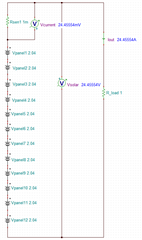
We like to install voltage and current sensors for telemetry data analysis of solar arrays.

Can you propose a solution of an electrical schematic diagram using voltage sensor LMO7704-SP and current sensor INA901-SP ?
How many voltage sensors and current sensors would be needed in each panel?
  • Hi Mya,

    How many voltage sensors and current sensors would be needed in each panel?

    Let me understand your design requirements. 

    Assume each solar cell is able to generate 0.51V with 0.7W of power, which means each cell is able to generate approx. 1.373 A/cell. 4 solar cell per string and 18 strings/panel, this will have approx. 2.04 V/panel and approx. 24.71 A/panel. 

    With 12 solar panel configuration, the total voltage is approx. 24.5Vdc and 24.71Adc total, if 12 panels are connected in series (these are typical voltage and current figures). 

    If the requirements are to monitor the PV's voltage and current in each panel, then the design will need a minimum of 12 op amps, say LMP7704-SP and 12 current monitor IC, say INA901-SP.  Please confirm this assumption. It will be good if you are able to supply a schematic for the possible solar panel configuration. 

    If you are only interested to monitor the system's output current, then only one current monitor IC is required.

    BTW, INA901-SP current monitor is supported by current sensing team and we may transfer your inquiry to the team for the support. However, please answer the following design questions. However, LMP7704-SP op amp is supported by our team. 

    1. What are the minimum and maximum solar cell's voltage and current when they are deployed in space.  

    2. What are available supply voltage rails  for LMP7704-SP and INA901-SP?  Are these supply voltage are from solar panel as well. 

    3. What are current sensing requirements for the application? Based on INA901-SP's requirement, shunt resistor is used? What is the required current shunt resistor value?

    4. What are solar panel configuration among 12 panels? Are panels always configured in series?

    Below is a simplified block diagram based on the current information and assumption, where the potential of each photovoltaic (PV) solar panel is measured and overall generated current is monitored in a series configuration in 12 PV panels.  The block diagram did not taken into any backup V and I monitoring system.  

    Best,

    Raymond

  • Here is the specification of solar cell and total solar array power.

    Each solar cell
    V = 2.73V
    I = 0.52 A
    P = 1.42W
    Each solar string (4 cells in series)
    V = 2.73 x 4 = 10.92V
    I = 0.52A
    Each solar panel (18 parallel strings)
    V = 10.92V
    I = 0.52 x 18 =9.36 A
    P = 102 W
    Solar array (12 panels in series)
    V = 10.92 x 12 = 131 V
    I = 9.36A
    P = 1226 W 
    The supply for LMP7704-SP and INA901-SP will come from PCU. 
    We still have no idea for current and voltage sensors circuit design. 
    Our requirement is to check each solar panel's health and performance.
  • Hi Mya,

    I'm Carolus from the current sensing team, and I support INA901. Looking at the arrays as you have them set up, the challenge will be how you wish to monitor these. As Ray points out, if you are only wanting to monitor the current of all 12 panels in series, a single INA901 would perform this. Be aware though, that the maximum common mode sustainable by the INA901 is 65V, which means that it would not be able to perform this measurement on the high side. It could however, be implemented on the low side with no issue. Do you know at what level you are looking for telemetry on the array? 

  • We have 6 panels on each wing of the satellite and the voltage for 6 panels each might be higher than 65V. So how about using one INA901 for 3 panels each so total would be required 4. How about LMP7704-SP?

  • Hi Mya,

    How about LMP7704-SP?

    The  input common mode voltage for LMP77-04-SP is approx. at 12Vdc, see the captured datasheet. This is the main reason that I forward it the current sensing/ monitor team.  

    I was wondering how the following solar cells are rated. Are these loaded or unloaded ratings? In other words, if one of the solar cell is connected to a load of 5.25Ω (with 2.73V/0.52A ), the solar panel is able to source 0.52Adc with PV voltage measured at 2.73Vdc (assumed under the optimum light to electron conversion in space). Solar panel is a current source. under a light loaded condition, the PV panel's voltage is high. Under a heavier load, the PV panel's voltage will droop significantly.  The light or no load condition is referring to Open Circuit condition. The latter one is referring to a closed circuit. 
    Each solar cell
    V = 2.73V
    I = 0.52 A
    P = 1.42W
    For a satellite application, the PV voltage will be high under light or no load conditions. Typically, a zenzer diode across each panel may be used to clamp down the panel's voltage (especially in outer space due to much stronger light intensity). The PV's voltage will continue to rise if light or no load is connected to the solar panels. 
    My 2nd question is that these panels are likely used to charge batteries (energy storage devices). What happened to the solar panel configuration if battery system is reached fully charged state. We are trying to understand the application requirements before we are able to design or recommend a solution. 
    All space qualified ICs are radiation hardening tested and certified, and the available qualified components for the application are limited. If the application is installed on the earth surface, we have a wide range of ICs that can handle the application. Since this is satellite application, we have less options and we are only able to design the application with the certified parts.  
    If you have additional questions, please let me know. 
    Best,
    Raymond 
  • 1. The solar cells are tested under unloaded ratings.

    2. We plan to design a shunting system when there is more power than required.

    If we install one INA901-SP for three solar panels and one LMP7704-SP for 6 panels, would it be a good solution?

    May I know the product lead time of INA901-SP and LMP7704-SP when shipping to Thailand or China?

  • Hi Mya, 

    The published lead time on the INA901-SP as of 01/28/22 is 6 weeks. We currently do have units in stock on TI.com. Ordering through TI.com will be the fastest way to receive units.

    -Kyle

  • Mya,

    I don't quite understand how you would implement an INA901 per 3 solar panels given your system configuration. If the 12 panels are in series, each panel as its added to the series would raise the respective voltage of the common mode seen by the amplifier. Dependent on where you implement the shunt, the voltage will still reach a level unacceptable to the INA901 inputs, and the current would still be the same value, as they are all in series:


    Can you elaborate a bit more on what you mean by implementing an INA901 per 3 panels?

  • Yes. Since our panels are connected in series, we cannot use a high-side configuration.

    Now we are designing a low side configuration circuit and choosing a shunt resistor value.

    Since we will give power supply to INA901-SP from PCU, we concern about the cables and wires from PCU to each panel. 

    Can you suggest us a shunt resistor, low side circuit and supply from PCU?

    Thanks

  • Mya,

    The choice of shunt and supply voltage will be made based off the needed accuracy and power considerations of the system. For the INA901-SP, up to a 16V supply voltage is recommended, but this may also be as small as 2.7V. My recommendation to you would be to check out the Current Sensing Calculator tool on the product page, and select the INA901 from the list inside the program. This will allow you to examine the full dynamic range error curve for various power supply considerations and shunt values (including tolerances), as well as power dissipations in the shunt at these various setpoints. As an example, I've generated the curve for a low side 5V supply with a 25mΩ shunt below:

    Let me know if you have any questions.