This thread has been locked.

If you have a related question, please click the "Ask a related question" button in the top right corner. The newly created question will be automatically linked to this question.

OPA657: Simulation error

Part Number: OPA657
Other Parts Discussed in Thread: OPA656, TINA-TI

Hi Team,

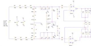
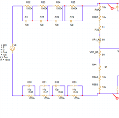
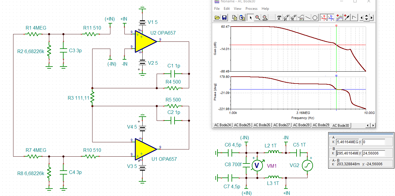
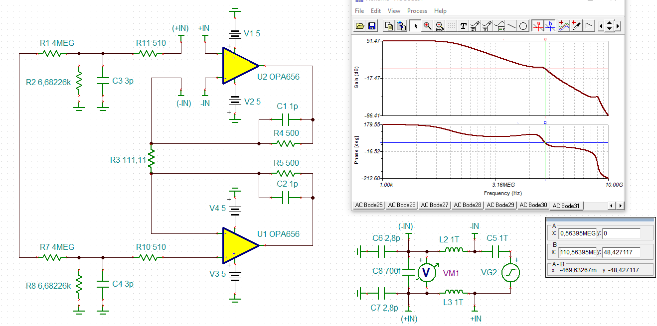
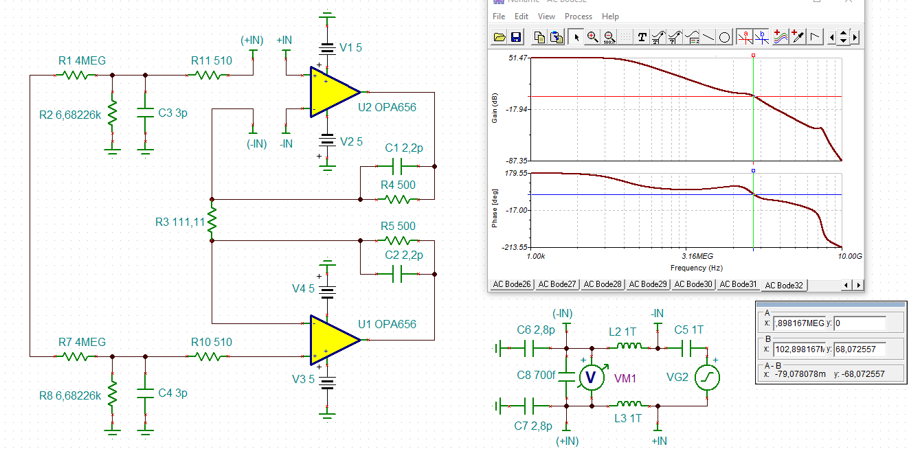
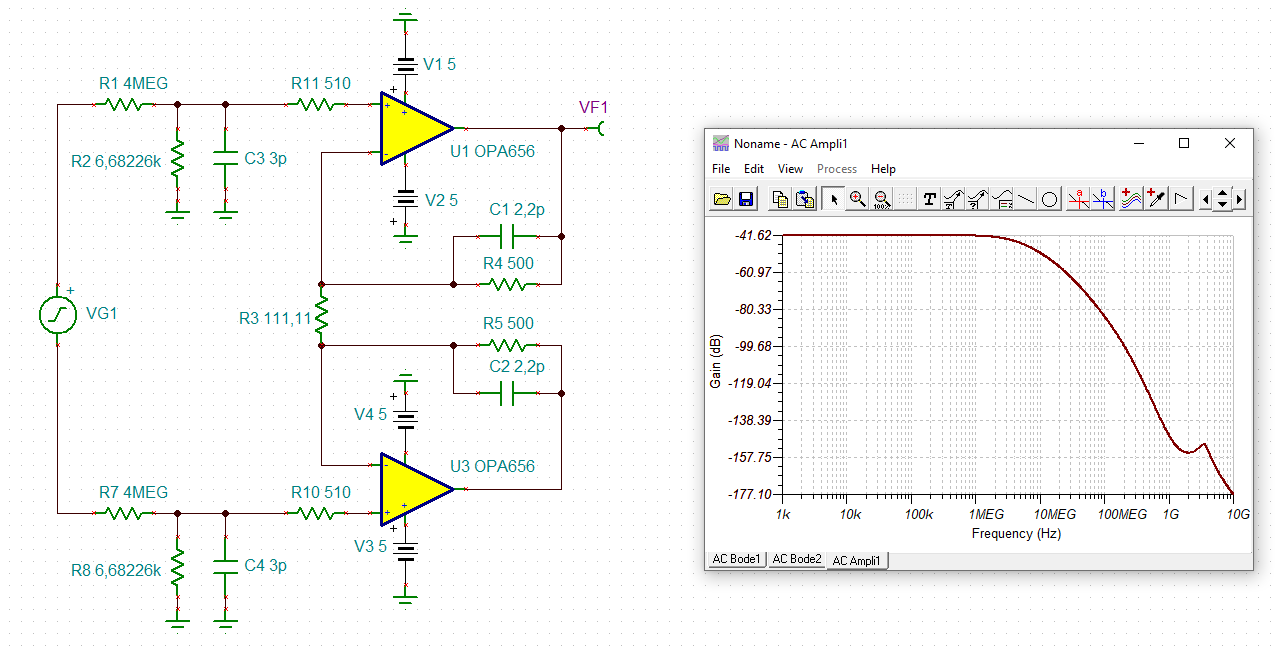
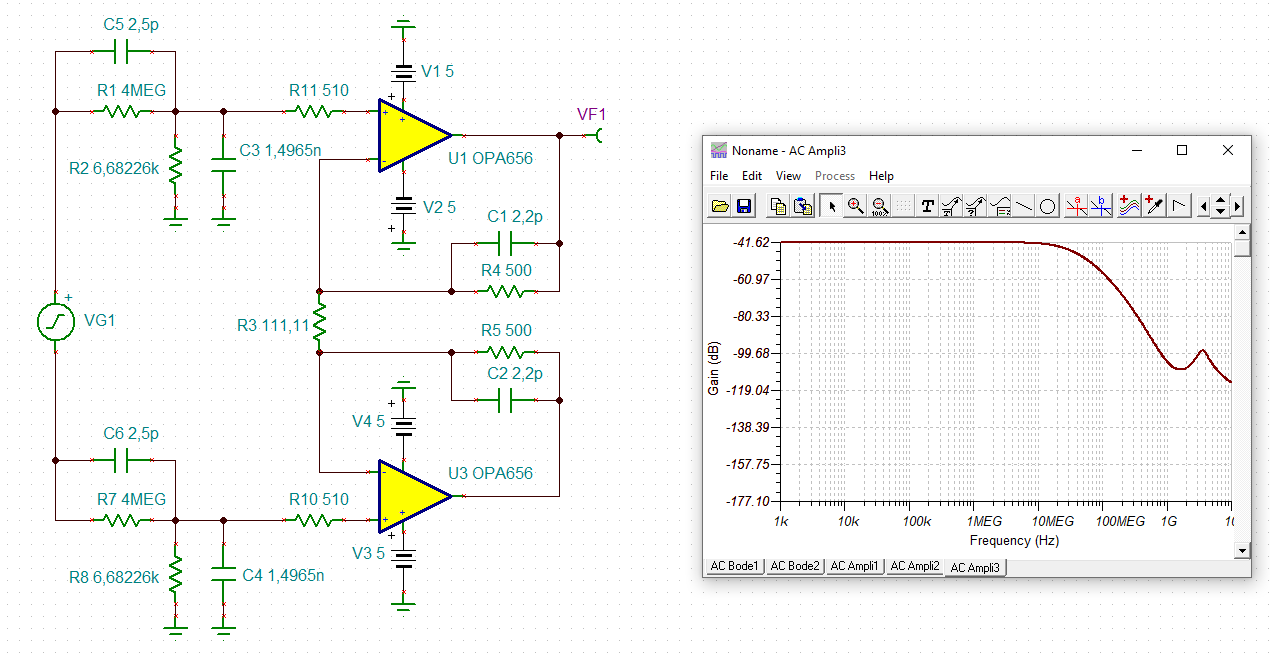
I plan to build a circuit to measure 400VDC pulse, to measure the exact voltage of the pulse, I am trying to use OPA657 to simulate, when there is only one OPA657 in the circuit, the pspice can run simulation, but when there are 2 OP657 in the ciurcuit, simulation cannot run and says "there are no data values in section number 1 ignoring this section". when i change to other low speed OP-AMP, no this issue. I need a op-amp with high speed, high input impedance and low input bias current.

Could you have a look what's the reason. Attached the circuit and pspice file for your referrence. 

Buy the way, in this circuit I don't use isolator, just use high value resistor divide 400VDC and get a low voltage common input to OPA657, is it safe for the OPA657 input? Thanks in advance.

.OPA657.zip

  • Morning Allen, 

    Sim issue aside, you are essentially doing a high impedance probe, need to set up your speed up caps across the passives correctly to retain response flatness to the amp inputs. It looks like the amps are set up for low gain, the OPA657 is not stable at low gain, a quick substitute would be the OPA656. 

    These JFET parts are good for high source R, and alternates would be available but would need the speed requirements and I/O voltage needs to set supply ranges. 

  • Hi Michael,

    Thanks for your help, I tried add  caps on the resitors, but the output singal has spike, attached picture are with/ whithout caps.


    And OPA656 has the same issue, simulation can run when only 1 OPA656, but failed when there are  2 OPA656 in the circuit, could you hlep have a look, thanks again.

    OPA656 TEST2.zip

  • Hi Allen,

    I have run a TINA-TI simulation. As Michael mentiones, the circuit isn't stable with the OPA657. The phase margin is only 25°:

    With the OPA656 the phase margin is 48°:

    And when increasing C1 and C2 to 2p2 the phase margin is even 68°:

    allen_opa656.TSC

    Keep in mind, that the above simulations will be incomplete, if an additional capacitive load is present at the outputs of OPAmp.

    Kai

  • Hi Allen,

    the frequency response of the circuit with the OPA656 would be:

    If you want to add caps in parallel to the 1M resistors, you will have to increase C3 and C4 as well to guarantee equal time constants, according to

    4M x 2.5p = 6.68226k x 1.4965n

    Resulting in:

    allen_opa656_1.TSC

    Kai

  • Thanks a lot Kai, I will change to OPA656 and adjust the capacitor value to simulate again.