This thread has been locked.

If you have a related question, please click the "Ask a related question" button in the top right corner. The newly created question will be automatically linked to this question.

THS4551: Gain

Part Number: THS4551
Other Parts Discussed in Thread: ADS127L11, THS4552, TINA-TI

Hi Team,

Our customer would like to know more information about connecting the THS4551 with ADS127L11. According to our customer,

I would like to know the gain band of the AOP THS4551, after the picture below in the DS :
See the picture Open-Loop Gain


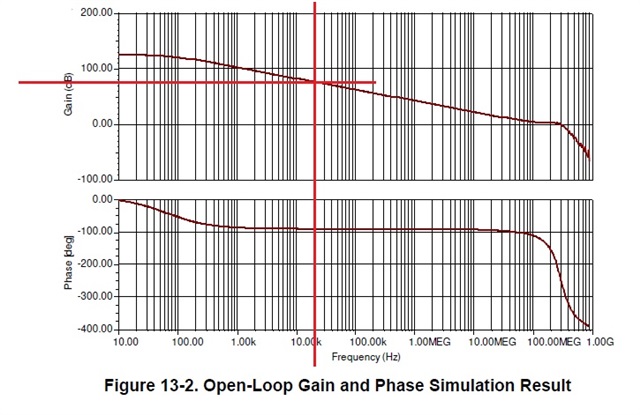
At 20 kHz, I have about 80 dB -> So the gain is 10^80/20 = 10,000.
So if I use this connection I can have a gain of around 10,000 right?

See the picture 'Attenuator Application'


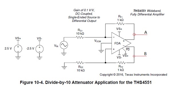
Of course this assembly is in attenuator but if I modify Rf1 and Rg1 I'll have the correct amplifier coefficient. For example if I need amplifier coefficient 1500 thus Rf1 = 15k and Rg1 =1k right ? Thanks for your help.

Regards,

Danilo

  • That is very strange question, you cannot run the FDA open loop and get that Aol gain, what gain do you want?

  • Hello Danilo,

     I believe the customer might be looking for the gain bandwidth product of the amplifier which is where the open loop gain of the amplifier crosses 0dB. For the THS4551, this is specified as 135MHz in the datasheet. Here is a link for a more detailed explanation and estimation towards the true GBP.

      Correct, RF and RG can be modified to change gain of FDA. The feedback paths (RF1, RF2 and RG1, RG2) should be symmetrical for optimal CMRR performance. Is the customer looking for a gain of 15V/V? What is their frequency range? 

    Thank you,

    Sima 

  • Hi Michael and Sima,

    Thank you for your response to this inquiry. According to our customer,

    Michael: 'That is very strange question, you cannot run the FDA open loop and get that Aol gain, what gain do you want?'

    Customer: I just need to know band gain function when using AOP before attacking ADC input.

    Sima: 'Is the customer looking for a gain of 15V/V? What is their frequency range?'

    Customer: I work in the frequency range up to 20 kHz with a symmetric power supply input +2.5V and -2.5V according in my previous answer.
    Please see in this picture 'Attenuator Application'.

    It's just an example but In the reality I use the same assembly but as an amplifier and not as an attenuator, because the signal coming from hydrophone is very weak. So I would like to know what is the maximum amplification coefficient (gain) that I can have for a frequency of 20 kHz. Do you understand what I'm trying to find out exactly?

    Regards,

    Danilo

  • Hi Danilo,

    yes, the maximum gain of THS4552 at 20kHz is about 80dB. But for good signal integrity (low gain error, low thermal gain drift, low distortion, low output impedance, etc.) you will need to have some linearizing gain reserve of let's say minimum 20dB, better 30dB or even more. How much precision and by this gain reserve you need depends on your application. So the maximum gain at 20kHz would be about 50...60dB.

    But take care, all this is only valid, if the signal bandwidth is strictly limited to 20kHz. If this is not the case, you will need to have this gain reserve for the higher frequencies as well, as otherwise you can suffer from intermodulation distortion. Then, it can make sense to decrease the gain of THS4552 even furtherly. 

    Kai

  • Hi Kai,

    Thank you for your inputs. Just want to check if you are pertaining to THS4551 and not THS4552? It seems like these are similar devices and the only difference is the number of amplifier in the package (single and dual). 

    Regards,

    Danilo

  • Hello Danilo,

      It could refer to both devices. Also, I would recommend to try out their design using Tina-TI or PSpice. The THS4551 has a lot of the Figures provided as simulation examples under the design and development tab. They could look into these files as a base, and increase the gain, as Kai said up to 50-60dB: Tina-TI Gain of 5 Single to Different Simplified for Figure 72 or with filtering: Tina-TI Gain of 5 Single to with 10Mhz Bessel Figure 93 and Tina-TI Gain of 0.2 100kHz Butterworth MFB Filter Figure 87.

    Thank you,
    Sima