This thread has been locked.

If you have a related question, please click the "Ask a related question" button in the top right corner. The newly created question will be automatically linked to this question.

BUF602: Single power supply issue

Part Number: BUF602
Other Parts Discussed in Thread: FDC2214, FDC1004

Dear TI experts,

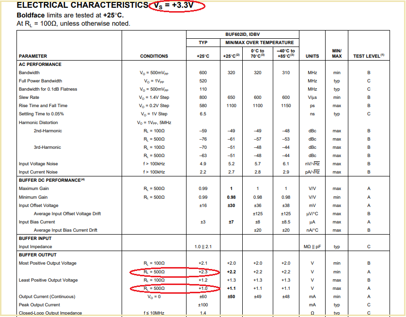
I want to configure the BUF602 to work on a single power supply mode.

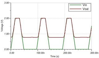
The datasheet shows that it seems that simply grounding the negative rail is sufficient, but the simulation results show that there is something wrong with the configuration.

Do I need to add some connection in to circuit?

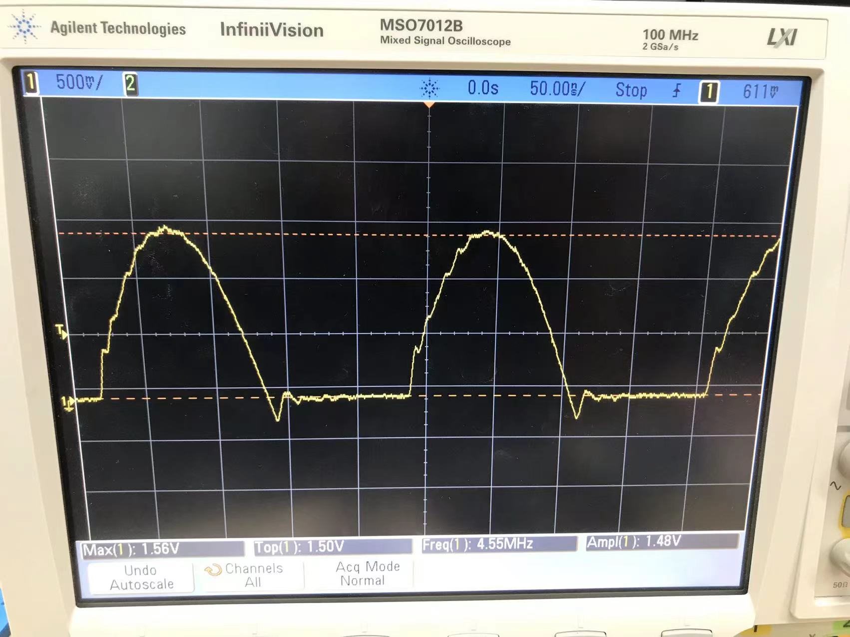
The input in the actual experiment is a half-rectified sine wave with a maximum amplitude of 1.8V and a frequency of 10MHz.

Power will come from the evaluation board's onboard 3.3V.

Best regards,

Will

  • Hello Will,

    I would start by requesting you tie the REF pin to GND, which in this case is V- on your schematic.  Please see my attached TINA file for details; could you elaborate on the load of your circuit and what you mean by 'something wrong'?  I would appreciate more information on your application, circuit load, and design need.

    buf602_single_supply_halfRectSine.TSC

    Best,

    Alec

  • Hi Will,

    unfortunately, you don't mention what is wrong with the simulation. Is wrong that the output voltage does not all the way go down to 0V? Datasheet of BUF602 clearly says that this is not possible with the BUF602. The most negative voltage is +1.0V:

    Kai

  • Hi Alec,

    Thanks Reply.

    The problem is that the output doesn't drop all the way down to 0V, which Kai mentions below.

    I want the output to be exactly the same as the input.

    Will

  • Thanks.

    Will

  • Hello Will,

    The BUF602 cannot go within +1V of GND.  With a 3V3 supply rail, it will be difficult to handle a 1V8 amplitude signal input without violating the amplifier specifications. 

    1. For 3V3 single supply, the minimum output voltage is +1.0V.  Even if you were to DC shift your input signal such that 'GND' for the rectified sine wave was at +1.0V for the BUF602 to correctly output, the 1V8 amplitude of your input would exceed the maximum output voltage of 2.1V (by driving up to 2.8V).  Are you flexible with using a different supply rail than 3V3?  Typically, buffers are unable to operate at the negative rail, especially on a single supply.  You could attenuate your positive amplitude to 0.9V, half of 1.8V, which would enable a +1V DC offset and prevent exceeding max/min output range specifications on 3V3 supply.  Your peak output would be at 1.9V, safely under the 2.1V max output limit.

    2. You could use a single 5V supply, and use a +1V DC offset to place your input signal within the 0.9-4.1V output range provided by the 5V supply.  This would enable you to keep the full 1V8 amplitude of your signal.  Your peak output would be 2.8V, safely within the 4.1V max output limit.  What source is providing your half-rectified sine wave w/ 1V8 amplitude at 10MHz?  Are you able to shift the signal or must the signal be at GND?

    3. If you would like the BUF602 to have an output matching exactly the input without modification to the input signal or output signal levels, you must use the BUF602 in dual supply mode (such as depicted in the attached image) to be able to operate from 0V to 1V8 without violating specifications.  Do you need to be able to perform this operation with single-supply?

    You may also be able to best accomplish your application with a different amplifier product, or a composite amplifier setup.  Your signal bandwidth of 10MHz is not fast enough to mandate use of a high-speed op-amp; you should use ti.com's Amplifier Product tool to search for the best device for your use case: https://www.ti.com/amplifier-circuit/products.html

    What are your output load and current requirements?  Another TI part may be a better fit depending on your design needs.

    Please let me know any further details about your application, and which aspects of your circuit design are not able to be changed.

    Best,

    Alec

  • Hi Alec,

    Thank you for the information.

    Dual power mode seems necessary if I'm going to use the BUF602.

    But my design could use other unity gain op amps as long as it can successfully buffer a 1.8V 10MHz half-sine signal from a single 3V supply.

    For my application details, the buffer is used to provide an active shield setup for TI's FDC2214 capacitance-to-digital converter. The active shield of the unity gain op amp needs to be connected to one side of the LC resonant circuit.

    The signal drive on the LC tank is a half rectified sine wave with a maximum amplitude between 1.2V and 1.8V. The maximum frequency configuration is 10MHz. The figure below shows an example drive signal on an LC resonant circuit with a frequency of 4.5MHz and an amplitude of 1.5V.

    So basically the rest of the circuit can't be changed, except the buffers.

    Since the active shield electrodes form capacitance with the ground plane of the PCB, the output load is primarily a capacitive load of around 10pF to 400pF, depending on the gap between the electrodes.

    The current needs to be as low as possible (less than 10mA) without distorting the buffered signal.

    For power settings, the final designed device will be fully battery powered, for example using a CR2032.

    But in order to realize the dual power supply mode of BUF602, two batteries can also be added in the design.


    Do you have any suggestion?

    Besr regards,

    Will

  • Hello Will,

    Thank you for all the information regarding your application and design needs.  I have a couple of points:

    1. You can also connect with the FDC2214 team on e2e; the consensus of the following threads appears to suggest the following:

    - If you need active shielding, the best choice is to use the FDC1004 which contains active shielding circuitry.

    - If you need the FDC2214, you may not need active shielding

    - The team supporting the FDC2214 has not been successful in finding an op-amp to recommend for providing active shielding for the FDC2214.

    See the actual posts in these threads:

    https://e2e.ti.com/support/sensors-group/sensors/f/sensors-forum/1050489/fdc2214-capacitance-jumps-and-active-shielding

    https://e2e.ti.com/support/sensors-group/sensors/f/sensors-forum/1009661/fdc2214evm-technical-query-regarding-fdc2214-evm---active-shield

    https://e2e.ti.com/support/sensors-group/sensors/f/sensors-forum/551536/fdc2214-active-shield

    https://e2e.ti.com/support/sensors-group/sensors/f/sensors-forum/815377/fdc2214-creating-an-active-shield-output

    https://e2e.ti.com/support/sensors-group/sensors/f/sensors-forum/928659/fdc2214-active-shield-with-an-external-op-amp

    2. If the BUF602 does not provide any additional performance to your need other than being unity-gain, I would investigate other op-amps since your application is low-current, relatively low-bandwidth compared to other high-speed parts.  You are correct that adding a second supply would enable proper use of the BUF602.

    3. If you decide not to use the BUF602 and pursue a unity-gain amplifier for this application, I would recommend looking at op-amps other than high speed op-amps based on your application.  You may find value with a precision amplifier or performant general purpose op-amp.

    My knowledge centers on op-amps and applications which are high-speed in nature, BW > 50MHz.  I do not work with this application day-to-day, so I do not have a particular op-amp recommendation for your application at this time.  I would contact the signal conditioning/sensor team over e2e to continue this discussion.

    Best,

    Alec

  • Hi Alec,

    Thanks for your reply.

    The FDC1004 is not suitable for my application as it only allows the sensor to work around 25 kHz.

    The experiments I'm doing require the sensor to work in the MHz region, which is why the FDC2214 was chosen earlier.

    The main reason to try an active shield is to make the sensor work as a unidirectional sensing mode.

    But it increases cost and power consumption due to the need to add an amplifier.

    So I plan to do some experiments to evaluate the blocking ability of the active shield to the interference of the non-senseing side, and to judge whether it is worthwhile to introduce the active shield.

    I would look at your suggested precision amplifiers and general purpose op amps to find a single supply op amp better suited for my application.

    Best regards,

    Will