This thread has been locked.

If you have a related question, please click the "Ask a related question" button in the top right corner. The newly created question will be automatically linked to this question.

OPA547: Current limit issue

Part Number: OPA547
Other Parts Discussed in Thread: DAC8734

Hi,

I'm using OPA547 as V to I converter with +/-15Vdc supply and a maximum current of +/- 50mA. I use 4 IC on the board in order to implement 4 V/I converter. The source is made by the 4 channel DAC8734 with the same power supply. 

The output current formula is: I = -Vdac/200 and is independent form the load.

I set the current limit to approximately 55mA by adding a 390k resistor between pin 3 and 4 with a 10nF capacitor in parallel.

I tested the output current with a 100ohm load and I see on 2 of 16 boards that 1 IC limit current is below 55mA: on one board is 38mA (3,8V on the load) and on the other is 47mA (4,7V). The issue is on 2 different V/I converter

I try to solder the OPA547 but the issue remain.

The DAC output is about -10V as I expect.

In order to improve the current limit until 50mA I had to put a 120k resistor which means about 160mA current limit!

On datasheet I see a tolerance of +/- 30mA  in current limit value for a load of 375mA.

Here are my questions:

1) the +/- 30mA tolerance is relative or absolute to the output current? Even if is absolute I don't understand why I need 160mA theroetical value to get 50mA output. I also try to chance the component but I have the same result (maybe also this has the problem)

2) How can I fix this problem?

Thanks

  • Hi Davide,

     How can I fix this problem?

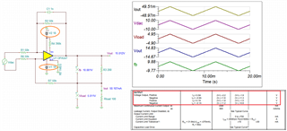
    Per your description, I think that you have Howland current pump configuration with OPA547, see the circuit below. 

    I think that issues may not have something to do with ±30mA tolerance specification (the application did not reach I_lim threshold). The current source is regulated by R3 or 200Ω and OPA547's Vout voltage.

    With Rload = 100Ω load, Vload = 5V. Since the OPA547's supply voltages are configured at ±15Vdc, the power amplifier's output voltage reached a saturation and unable to go higher, where Vout = Vfb + Vload for Iout = 50mA. The datasheet is specified Io = ±100mA, but your ±50mA have the similar Vout swing limits. 

    OPA547 Howland I 03162022.TSC

    To get around the issues, you may have to increase your supply rails slightly. Or lower your Rload below 100Ω.

    Enclosed is a Howland Current Pump app note for your reference. Note that I did not buffer the OPA547's feedback and I have to use large feedback resistors to reduce the current errors in the simulation. 

    https://www.ti.com/lit/an/sboa441/sboa441.pdf?ts=1647448729747&ref_url=https%253A%252F%252Fwww.google.com%252F

    If you have additional questions, please let me know. 

    Best,

    Raymond

  • Hi Davide,

    you shot show your schematic. Without schematic we are blind and have to guess Relaxed

    Kai