This thread has been locked.

If you have a related question, please click the "Ask a related question" button in the top right corner. The newly created question will be automatically linked to this question.

LPV821: Suitable op amp for voltage reference using REF5020

Part Number: LPV821
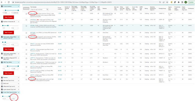
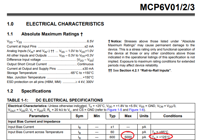
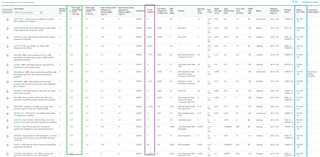
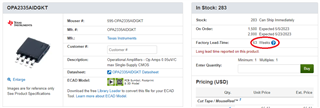
Other Parts Discussed in Thread: ADS1219, REF5020, , OPA320, OPA388, OPA350, LMP91000, OPA2378, OPA2335, LMP2232, TLV2262, OPA2336, OPA2340, OPA2320, LMP2012, OPA2328, OPA335, LM4140, OPA2187

Hi

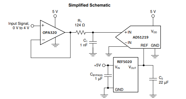
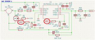
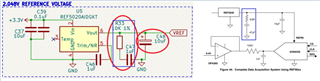
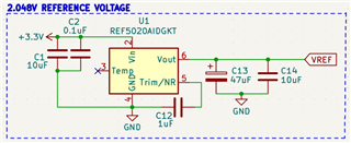
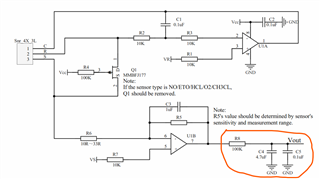
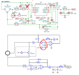
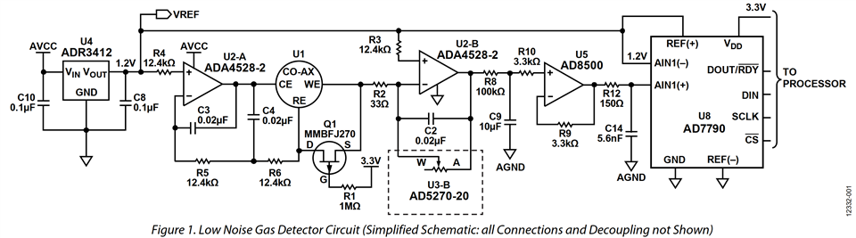
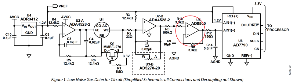
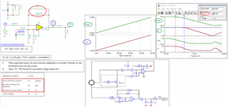
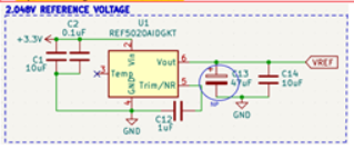
I have designed the circuit below based on the available datasheets and EVM schematics. I am not an engineer. I need help with the design below.

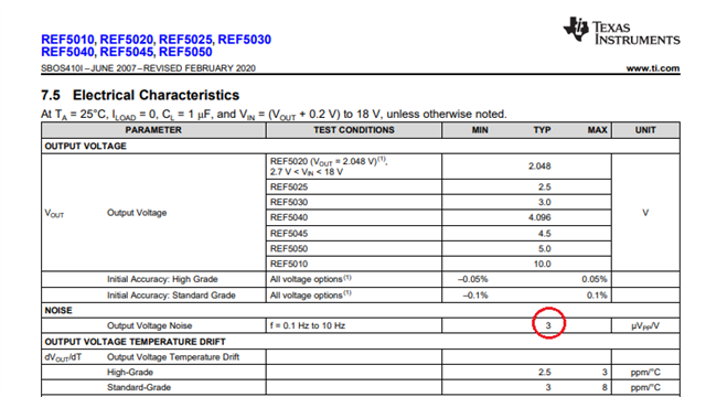
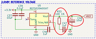
I want to drive the REFP of ADS1219 24 bit ADC. Please let me know if the design is fine. I am planning to use 10uF tantalum capacitor on the output.

Regards

Vijay

  • Hello Vijay,

    Are you talking about a 10 uF capacitor for C48 at the REF5020 output, or one not shown in the schematic but at the LPV821 output (VREF)? 

    The Data Converters e2e forum group can usually provide the most complete information about driving the REF pin on a converter such as the ADS1219.

    Regards, Thomas

    Precision Amplifiers 

  • Vijay,

    The main issue with your circuit I see in the use of a micro-power LPV821, which with 215nV/rt-Hz noise spectral density will totally dominate the noise at the REF pin. 

    The total noise of the LPV821 will be 115uVpp [215nV/rt-Hz*(8kHz)^.5*6]  limiting the resolution to 14 bits. For comparison, the output noise of REF5020 is 6.14uVpp (3uV/V*2.048V).

    Thus, instead I would suggest a circuit like the one shown below but as Tom suggested the best would be to get confirmation from Data Converter E2E support team.

  • Thank you so much. I will post this with Data Converter support team as suggested. 

  • The OPA320 is not available. Can you please suggest an alternate part that is available? Also can you please let me know the requirement parameters for searching op amps for this purpose?

  • Vijay,

    For driving the input of 24-bit resolution system, low input voltage noise, low offset voltage and fast settling time would be important.  For driving REF pin, in addition to above list a high capacitive load drive would also be critical.  Our Data Converter support team may have few other recommendations.

    Below please see few available parts from our Precision Linear product line. Unfortunately, two of the three are currently only available in a dual version. 

  • Thanks Marek. Is OPA388 suitable? It is cheaper than OPA350 and easily sourced. I only need a single channel op amp. The Data converter team suggested that there may not be a need for op amp to drive the ADS1219 as REF5020 has enough drive capability. Please see link below and advise.

    https://e2e.ti.com/support/data-converters-group/data-converters/f/data-converters-forum/1091491/ads1219-suitable-op-amp-for-voltage-reference-using-ref5020-to-drive-ads1219/4041902#4041902

  • Vijay,

    You do NOT need a buffer between the REF5020 and REF pin of ADS1219 and in the simplified schematic above I had showed REF5020 directly driving the converter REF pin.  As far as buffering/filtering of the input signal in front of the converter using OPA388, you may be able to do it if the settling time is not the most critical. OPA388 uses an auto-calibration technique with a time-continuous, 200-kHz operational amplifier in the signal path, and thus you may need to optimize the compensation at the output of OPA388 to meet your timing/resolution requirements.  Even though the simulation below shows the small-signal setting time to 16-bit resolution (31uV) of about 1us, the OPA388 macro-model does NOT include auto-zero action of the chopper amplifier (with 5us delay between the auto-correction cycles) and thus the actual settling time may be longer.

    For more insides into the use of chopper amplifier in front of ADS1219, please contact the Data Converter team.

  • Thank you Marek for you time. I think I will avoid the op amp to make this less complicated. This is what the data converter forum suggested too.

  • No problem.  Good luck!

  • One last question. I am not sure if you have seen the link to my question in the data converter forum. The REF5020 is also connected to input of 4 dual channel op amps (MCP6V02) with a low input bias current of +1 pA. I will be connection 4 op amps and one ADS1219 to the REF5020. Will REF5020 need a buffer in this case.

    I hope the vref circuit above is fine.

    Regards

    Vijay

  • With the 10uF cap on REF5020 output pin, I would not think you need to buffer it in order to drive Vref of linear op amps BUT MCP6V02 is an auto-zero op amp with the internal 300kHz clock that corrects its offset, which may generate IB spikes feeding back into REF pin of the ADS; thus, the jury is still out whether you need to buffer the four input of the MCP6V02 and the only way to make sure is to actually build the board with the option for buffers and verify its performance with and without them.

  • Hi Vijay,

    Will REF5020 need a buffer in this case.

    The attached schematic looks like that REF5020 is going to source 2x(2.048/20kΩ) = 205uA. You may neglect the currents go into 4 x op amps. It is likely that REF5020 is able to source up to 500uA with insignificant droop at its output terminal. 

    If you are able to increase the value of voltage dividers, you may further reduce the current sourcing out of REF5020 (say use 50kΩ resistor dividers or slightly higher) and the reference will be good and stable over temperature.

    REF5020's Load regulation is specified in the table below, and REF5020 is capable to source or sink in ±10mA. You will be ok, if you do not increase 10kΩ resistor. REF50XX is a very good selection for the voltage reference.  

    The REF5020's output reference does not look right. You should use low ESR 0.1uf, where ESR is typically low up to 10mΩ. In Figure 44, 47uF is used with low ESR  capacitor (this is a part of damping network for high speed DAQ application). If your sampling rate is low, it is likely that you do not need it. The larger 47uF with low ESR capacitor will reduce the ripple of the REF5020, and stabilize the REF5020's output (It should not hurt). You may verify its function with a scope measurement --> check the ripple amplitude at the output of REF5020. 

    Best,

    Raymond

  • Marek and Raymond 

    At the outset I sincerely thank you for your time. I truly appreciate it. I like to inform you that I am a medical doctor by profession and trying to design this PCB as personal project to develop an affordable opensource device that will help monitor indoor air quality that has become a major health concern. I am comfortable at software coding and my knowledge in electronics is very little. I am trying to design the PCB as the we have already gone through 4 designs earlier due to shortage of components with consultants and they got tired. The original design was based on LMP91000 and we also built and tested the prototypes. Now the LMP91000 is not available for over an year. Even the ADC we used had to be changed twice and LTC6655 was replaced with REF5020.

    If my budget permits, I will be distributing these devices to be used with RPI, ESP32, Arduino etc. to all education institutes free of charge and sell them at cost to DIY enthusiasts with free access to IoT portal on the cloud. So all help here is greatly appreciated.

    The sampling rate I am planning to use with ADS1219 is 20 SPS which is quite low. I was following the guidelines from the REF5020 datasheet which says that the recommended ESR on the output capacitor is from 1 Ohm to 1.5 Ohm. I can go higher from 10uF to 47uF as you suggested.

    Taking Marek and your suggestion, I think the circuit below should be good to go for prototype purpose. Already some of the components in my Mouser cart are disappearing Sweat

    Please also review the attached schematic for the full PCB if your time permits.

    Thanks & regards

    Vijay

    https://www.ecosense.se/docs/GasSensorShield.pdf

  • Hi Vijay,

    You may leave C13 or 47uF electrolytic capacitor as NP (not populated). For your 20SPS ADC application, REF5020 with low ESR C14, 10uF ceramic capacitor at output should be sufficient. 

    1Ω <= ESR <= 1.5Ω in series with 1uF to 50uF capacitor is a damping network. Your application is not needed. Figure 44 in REF5020 datasheet refers to the 250ksps DAQ system. 

    I am unable to support our competitor's op amp product. As any op amps, it does not like to drive capacitive load directly. It may create an op amp feedback instability at the output. You should request Microchip to review MCP6V02 schematic for the sensing application. In addition, the cutoff frequency (LPF) from R30 and C34 (fc = 1/(2*pi*100kΩ*10uF)=0.16Hz) seems low of a gas sensor's response time (my guess sensor should have approx. 1Hz response time or higher).  

    I assumed that our ADC support team will help you to review ADS1219 schematic for the application. 

    If you have additional questions, please let us know. 

    Best,

    Raymond

  • Raymond

    The response time is very long typically < 30 seconds (far below 1Hz) for almost all the electrochemical gas sensors in the market. C30, R30 and C34 were suggested by the gas sensor manufacturer. As suggested, I will request Microchip for further advise. Thank you for your time.

  • Hi Vijay,

    Raymond is right, the datasheet of MCP6V02 says that a capacitive load of 100nF must not be directly connected from the output of OPAmp to ground.

    Can you show the original schematic? I ask because a few points of the shown schematics above look confusing to me.

    Also, what gas sensor are you using?

    Kai

  • Kai

    Please see the link below for the complete schematic

    https://www.ecosense.se/docs/GasSensorShield.pdf

    Below is the link to Semeatech gas sensor datasheet.

    https://semeatech.com/uploads/datasheet/4series/051-1200-000_EN.pdf

    Components rating is based on what is available with SMT. If any ratings have to be changed, please let me know. The sensor manufacturer Semeatech has confirmed that the design looks good but could not advise me on the point Raymond raised. I think if this one issue is solved, we can go ahead for prototyping. Though this design is specific to Semeatech sensors, changing the values of RL and RF resistor should allow us to use the same circuit with Alphasense, Membrapor and similar 3 wire electrochemical sensors. Thank you.

    Regards

    Vijay

  • Raymond. The C30 capacitor has been suggested by the gas sensor manufacturer. If I remove the C30, will it resolve the feedback instability issue? Also in the schematic shared by Semeatech, they originally had the C30 after R30.

    Is placing the C30 after R30 better?

    Thanks and regards

    Vijay

  • Hi Vijay,

    The circled orange LPF filter is ok, but you only need to keep one capacitor after R8 or 100kΩ, either C4 or C5 or a different Capacitor value as post LPF. 

    If you want to use Microchip's op amps, I would recommend that you ask their team to simulate the circuit for you. Or you should place the CO sensing circuit on a breadboard or PCB to check it out. The circuit you posted in pdf is slightly different from the manufacture's schematic.  

    I think that the gas sensor's output is in mV,  where the WE electrode or the circuit has a gain of -909.1V/V (30kΩ/33Ω).

    If the CO sensor's output is sourcing or sinking in current via a redox reaction, transient impedance amplifier (TIA) is typically used to convert current to voltage (I-to-V convertor) in a 3-electrochemical cell. 

    If you have additional questions, please let us know. 

    Best,

    Raymond

  • Originally, we had an option of designing the circuit with either OPA2378 or MCP6V02. However, the OPA2378 is out of stock. I have not got response from Microchip yet. If MCP6v02 needs to be replaced, I can do it. I have already been changing parts for the past 2 months Sweat smile

  • Hi Vijay,

    Let me see if I am able to find a p2p replacement (OPA2378) for you tomorrow. Yes, it is difficult to find IC components in the current environment. 

    What is the output voltage range from CO gas sensor? The sensor's response time is approx. 30-40 seconds. 

    Best,

    Raymond

  • Max output voltage of the sensor is equal to the sensor sensitivity x maximum range. For eg, CO sensor the sensitivity is 0.5 mA/ppm (+1mA/ppm) and maximum range is 50 ppm.

    SEMEATECH SENSOR CO Gas     SO2 Gas     NO2 Gas     O3 Gas  
    Sensor Sensitivity (Isense) 0.6 μA/ppm 0.6 μA/ppm -0.75 μA/ppm -1.1 μA/ppm
    Max Sensor Range from Datasheet 50 ppm 20 ppm 20 ppm 10 ppm
    Max Sensor Current (Imax) 30 μA 12 μA -15 μA -11 μA
    Output Voltage 30 μV   12 μV   -15 μV   -11 μV

    If you are finding a replacement part, please make sure that it is abundantly available in the market with short lead times. Last time we had LMP91000 for prototyping but when wanted to go for production the part was not available, Otherwise, I prefer to stick with the present design and resolve the issue.

    Regards

    Vijay

  • Hi Vijay,

    placing C30 directly at the output of OPAmp is definitely a mistake as I already mentioned above. If C30 is still needed in parallel to C34 depends on what sort of components you want to use. If you want to use a tantal for C34 then an additional 100nF X7R can make sense. But if you want to use a 4µ7...10µ X7R no further 100nF X7R would be needed. ("X7R" means the use of a ceramic cap made of X7R dielectric material).

    This brings me to my next question: Do you want to take SMD components or through hole in your project?

    Kai

  • A good replacement for MCP6V02 would be OPA2335 - see availability below.

  • Raymond / Kai / Marek

    Thank you for your great support. We are using SMD components. Please refer to Semeatech application notes.

    AN161205.pdf (ecosense.se)

    We need op amp with very low input bias current and low input voltage noise. I think we will stick to MCP6V02 unless we can find similar or better than this part. We will remove the C30. It is not required. Will it be OK to drive the signal to the ADC without C30?. If it is OK, we can go ahead with the prototype.

    Some of the parts in my cart including ADS1219 are going low in stock. I don't want to end up redesigning the whole circuit again. The PCB design is already done. We are waiting for finalization of the circuit to order the pcbs.

    Regards

    Vijay

  • Hi Vijay,

    Here is a typo in the pdf schematic. You may leave it unpopulated, if the PCB is already made. 

    We have very wide selection of low Ibias precision op amps for 3-electrochemical electrode interface application. If you change your mind, please let us know. You should ask Microchip to simulate the circuit with the selected op amps and make sure that there are no surprises.  

    Best,

    Raymond

  • Vijay,

    MCP6V02 is not exactly low IB - its maximum IB is not specified at 25C and at 125 deg C it can be as high as 5,000pA - see below.

  • I will be happy to change the design if this resolves everything. Frankly I now have zero clue of the whats right or wrong with the design. The Alphasense sensors asked me to follow the circuit design below.

    This circuit is supposed to work with all major sensor manufacturers. Semeatech confirmed that the TIA part of the design is good. But I myself don't know much about that. The present design has evolved through many changes from the basic circuit above mostly due parts availability.

    Since all the sensors have more or less similar specifications, I think we can have a generic design that can work with most of them. If you think that changing to OP2335 will finalize the design, I will do it and send the final circuit for review. This will increase my BOM cost substantially because the OP2335 ($4.30) is almost twice the cost of MCP6V02 ($2.70) in Mouser. MCP6V02 is $2.50 and OPA2335 is $3.675 for quantities of 100. The circuit uses 4 of these and this is a substantial cost increase. However, since our first production is 1000 pcbs, this cost increase in small order can be contained.

    Please let me know the final changes to the circuit with OPA2335. I will make the changes and revert back to you.

    Regards

    Vijay

  • U5 is not required in case of buffered ADC. I have not used an op amp in the circuit as ADS1219 input is buffered. Please correct me if I am wrong

  • Marek

    This product is for indoor use where temperature is around 25C. Beyond that I will be more worried about the sensors which have max temp of 50C. Realistically there will be no situation where they will be exposed very high or low temperatures. So between 25-50C it is much lower than OPA2335.

    MCP6V02

    OPA2335

    Regards

    Vijay

  • Vijay,

    MCP6V02 is an auto-zero op amp with auto-correction of the offset voltage every 100us (10kHz), which will generate IB spikes just like OPA2335, which will be integrated over time to something much higher than 1pA.  Thus, I am very skeptical of their IB claim of 1pA at 25deg C especially since you may notice the Ios shows as 30pA at 25C and 35pA at 50 deg C.  Since Ios = (IB+) - (IB-), this would mean that IB- must be -34pA at 50C.  Also, keep in mind that all typical graphs are just that - TYPICAL - and the maximum IB values might be much higher than what the typical plots show. 

  • You are a better judge. I was only looking at the input bias current as that is what was mentioned as most important by both Alphasense and Semeatech. I just wanted to inform you that our devices will mostly be operated between 5-45C at most. So if you think that OPA2335 is a good replacement I am good to go. I am just waiting for feedback from Raymond and Kai.

    Regards

    Vijay

  • Hi Vijay,

    I simulated the last stage of TIA as shown below. The Cf capacitor may go from 220nF to 1uF range, since CO sensor's BW is below 0.05Hz. 

    In the simulation, WE's oxidation current is simulated from 100pA to 50uA, and the TIA's corresponding output is from 1.024V to 2.524V. If you want to maximize the ADC range, you may increase the R_gain resistor up to 3.3V/50uA = 66kΩ range, see the linear relationship of the Vp or Vout vs. Ico or input current. 

    Of course, you will need to perform 2 point [CO] concentration calibration within the CO sensing range once boards are made. 

    Please see the attached file in Tina simulation below. 

     OPA2335 TIA WE 04122022.TSC

    We have a wide selection of TIA op amps for various application. Below is the link that you may be able to find other suitable parts in TI Store. It looks like that you are using SOIC-8 dual op amp packages, which are one of popular packages from the selection. If you are looking for cost competitive op amps in our catalog, you can find from the link below . Or you may get help directly from E2E forum. 

    https://www.ti.com/amplifier-circuit/op-amps/precision/products.html#p480=2;2&p3270typ=-4.9;5&p3271typ=-0.4;0.1&p1261max=5;180&p1261min=1.6;5&p89=FET;CMOS&sort=p1261max;asc

    I will try to simulate the CE and RE electrodes in TIna by tomorrow.

    If you have additional questions, please let us know. 

    Best,

    Raymond 

  • At outset you are all fantastic. Thank you so much all of you for taking time to help me out even though I am a total newbie. The only thing that worries me about OPA2335 availability in future.

    This part is already low in stock with the distributors and there is a long lead time. We may need at least 2 months for the PCB to be assembled and tested before we go for full scale production. Even if we go for a production of 1,000 pcbs, we will need 4000 OPA2335. If the stocks at the distributors are exhausted by then, we will need to wait over a year for these parts. Before we finalized on ADS1219, this was the major criteria to decide. The lead time was just 8 weeks.

    Part No. In. Bias Cur. Offset V Noise µVP-P  Price  TI Mouser Lead Time
    LMP2232 1.00 pA 0.150 mV 2.40  $    1.000     221,630 1373 6 weeks
    TLV2262 60.00 pA 2.500 mV  $    0.609     176,921 585 52 weeks
    OPA2336 10.00 pA 0.125 mV 3.00  $    1.065        54,936 1500 30 weeks
    OPA2340 10.00 pA 0.500 mV 8.00  $    1.516        38,309 164 83 weeks
    OPA2320 0.90 pA 0.150 mV 2.80  $    1.200          8,000 2500 14 weeks
    LMP2012 4.00 pA 0.036 mV 0.06  $    1.210          3,395 1270 70 weeks
    OPA2328 1.00 pA 0.025 mV 3.00  $    1.400          1,775 0 ???
    OP2335 200.00 pA 0.005 mV 1.40  $    2.076        31,013 283 63 weeks

    Based on the link you sent me and the future availability of the part, LMP2232 seems to be a better bet for now if it can be used to replace MCP6V02. Please confirm. I can start working on the new design with LMP2232.

    Regards

    Vijay

  • Please see attached doc for sensor model for simulation.

    Amperometric Gas Sensor Model.pdf

  • Below was the email from Semeatech.

    They said the VOUT=VREF=ADC FS. The gain resistor value is calculated to get a max VOUT of 2.048V. CO gas has a maximum current output of 30uA. I am not sure if we can increase the R_Gain value to 66K as this will increase the VOUT to 3.004V (1.024V + (66000Ω + 0.00003A)).

  • Vijay,

    The main reason behind using auto-zero op amps like MCP6V02 or OPA2235 was their very low offset voltage BUT if you plan to calibrate the system (to remove the offset related error) you should be able to use LMP2232.

  • Can I use a low ESR 10uF tantalum capacitor for C13 and not place C14? I am not able to find a low ESR ceramic capacitor in smaller packages. REF5020 is also out of stock now. I am only left with the high grade.

  • Hi Vijay,

    Regarding to R_gain resistor, the TIA's gain may increase up to approx. 75kΩ for 3.3V ADC input range. 1.024V is the output voltage when there is no [CO] concentration in an environment.  

    Regarding the CE and RE electrodes (assume D series CO), this is what I have. The op amp feedback loop is stable with OPA335. Capacitor C2 may be 10nF to 100nF, and I selected 33nf. Since the application does not require high BW, I did not select low value or 10nF. I picked 33nF with BW of 482Hz at CE electrode side. With C2 = 100nF, the BW is reduced to approx. 159Hz. The phase margin of the circuit is not an issue, which is at 90 degree. 

    OPA2335 CO Sensor CE AC Analysis 04132022.TSC

    Regarding to the other schematic shown in some of reference designs at CE/RE electrodes, these are all op amp compensation scheme to stabilize the selected op amp used in the application. I think that company recommended these configurations (somewhat generalized it), so that users does not require to simulate the circuit, think of as circuit receipt. Without simulation, it probably will work for such low BW application, but the circuit is not optimized for the op amp used for the application. 

    Can I use a low ESR 10uF tantalum capacitor for C13 and not place C14? 

    Are you referring to the schematic? Since your application does not go high temperature beyond 50C, 10uF low ESR Ta capacitor will be ok. If you have C14 = 1uF low ceramic capacitor, you may place it two capacitors in parallel. Otherwise, it will likely work ok without C14.   

    If you have other questions, please let us know. 

    Best,

    Raymond

  • Raymond

    Thank you for the information. I am finally thinking to keep the MCP6V02 op amp as almost all the TI op amps that I can use are almost out of stock and have very long lead times stretching to over 50-60 weeks. Now REF5020 also is out of stock which is pushing me back to redesign of the circuit with a new voltage reference. This is all so depressing. I have been working on this one problem since past 2 months and with 4 major design changes. It is only a matter of time when ADS1219 will also goes out of stock. It is unfortunate that none of the sensor manufacturers could give single reference design that we could adapt. The design task has become so difficult due to the non-availability of the parts.

    If possible and if your time permits, please give me one circuit design with whatever changes it needs and with which I go ahead with prototyping. I am fully aware that there can be further changes to the design after testing the prototype. I do not mind changing any of the components in the circuit as long as they will be available in the market for bulk production. I have already replaced the REF5020 with LM4140. The schematic shows both REF5020 and LMP4140 but only one of them will be used.

    Gas Sensor Shield

    Regards

    Vijay

  • Hi Vijay,

    The design task has become so difficult due to the non-availability of the parts.

    Yes, certainly is. Many customers replenish the low risk parts in a given design and finalize the remaining circuit in the current environment. You may also consider 2nd or backup components in case of part shortage. 

    If possible and if your time permits, please give me one circuit design with whatever changes it needs and with which I go ahead with prototyping.

    I have informed you that the sensor manufacturer's reference design will work for many op amp selections. Every op amps are different (BW, phase margins and others); some will compensate a slightly more than others. For the low BW application, the general purpose CO reference design may be good enough. However, you should ask the manufacture to check the final design. If you decided to use Microchip op amps, you should ask their engineers to check the design for you. 

    If you have other questions, please let us know. 

    Best,

    Raymond

  • Raymond

    Thank you for understanding. Our target is to have at least 1,000 devices working if this prototype works well. Unless the components are available for scaling up production it beats the purpose of this design. We already lost a year with LMP91000.

    LMP2232 is the one that is available for now and for production later, but Marek said we need to calibrate the system. If this is a one process with each PCB we should be okay. All other op amps have very long lead times. If you think we can optimize the design with LMP2232, we should be good to go. We also need guidance on how to calibrate the system. Please suggest if there any other suitable op amp for my application that I have missed.

    I also like the idea of backup components. However, I am not sure if there will be components that will have matching footprints and specs to replace one another without redesigning the PCB. If this is possible, I am open for the idea.

    Regards

    Vijay

  • Hi Vijay,

    In my experience, all precised electrochemical based measurements require calibration (redox reactions are associated with many external variables). For the CO sensor, you need to contact the manufacturer if the sensor calibration is required. If the purpose of CO measurement is to warn [CO] in a closed environment, then the [CO] calibration may not be required (it does not hurt either), but the sensing device has to be operated consistently and reliably over time within a temperature range. 

    In addition, [CO] gas calibration may or may not be cost effective steps for manufacturing a product. It is possible to null out the Voffset of CO's TIA output electronically (as a part of electronic calibration), which it may be more manageable. 

    Please let us know how you'd like to select suitable op amps. I know that you are dealing with availability issues, price to performance issues, design stability issues etc., I can suggesting some options. In terms of op amp package, you had SOIC-8 package designed on the PCB, which is widely available package in op amp products, and we have wide selections of precision op amps than any manufactures in the market.

    Since many of our top seller op amps are very popular among different industries, this is a part of reason that you have difficult time to find stocked items. And you should plan ahead for the current manufacturing environment. The lean-production manufacturing approach does not work in the recent manufacturing environment. 

    As TI customer, we are obligated to assist you. However, I am unable to support a design if you are selecting op amps from a different manufacturer.  

    Best,

    Raymond 

  • Hello Raymond

    Gas sensors are already calibrated by manufacturer. Since this product is not for industrial use, we do not need very high accuracy. The sensor sensitivity itself has an error of over 20%. We just do not want to add any more error though electronics. If we can null out the Voffset, it should be okay. The product is also meant to be used indoors, so we are not expecting extreme temperatures. It will mostly be operating at normal room temperatures and the temperature may vary between 10C-40C in non-airconditioned spaces.

    List of op amps I mentioned were from the link you gave me. Suggested OPA2335 has high input bias current which the sensor company said is not desirable. Also this part has a very long lead time of 52 weeks but currently TI has around 10K in stock. I can go ahead and use this part. It takes around 2-3 weeks to order the sample pcbs and probably another 2-3 weeks to test them. If you have any other part in mind please let me know.

    My only question is will it be possible for you to help get complete solution if we change the op amp. I have already replaced the REF5020 with LM4140 for voltage reference.

    Regards

    Vijay

  • Hi Vijay,

    U5 is not required in case of buffered ADC. I have not used an op amp in the circuit as ADS1219 input is buffered. Please correct me if I am wrong

    Yes, the ADS1219 has input buffers, but its input bias current of 5nA would cause a too high voltage drop across R8. This would degrade the input offset voltage of ADS1219:

    So an additional buffer is needed with a much lower input bias current. Then you have both, the heavy low pass filtering of R8 and C9 and the smaller voltage drop across R12, because R12 is so much smaller than R8.

    Kai

  • Kai

    I think the only way this can be circuit design can be finalized is to get complete circuit design from TI. No one will ever know TI products better than TI engineers. Even the sensor manufacturers are asking me to contact the component manufacturer to finalize the circuit design. Please let me if I can seek complete circuit design from TI.

    Regards

    Vijay

  • Hi Vijay,

    Due to the op amp availability issues, I am unable to tell you what is the best options for the CO design requirements. Here is the op amp minimum requirements. 

    Based on your CO sensor, which it has 0.16uA/ppm sensitivity. Typical [CO] in atomsphere is between 0.12ppm to 0.6ppm. Typical indoor [CO] is between 0.5ppm to 5ppm.If we pick 0.12ppm as a nominal level for your application, the CO sensor will generate approx. 0.16uA/ppm*0.5ppm = 80nA., assume 0.5ppm residual [CO] at indoor. 

    The Ibias_min current for the selection of op amp is between 80pA to 800pA range approximately, say 10C < Tamb < 50C.  

    Second op amp consideration is the drift over time. Auto-zero op amps (e.g. OPA2335, OPA2187 etc.) will be a better choices than chopper amplifiers or non zero-drift precision op amps for the application. I have provided you with a n op amp links that you may select from. 

    There are other key parameters that may be important to you. We may discuss a simulation once you have finalized these component selection, otherwise, current situation is going to change again in coming weeks. 

    Best,

    Raymond