This thread has been locked.

If you have a related question, please click the "Ask a related question" button in the top right corner. The newly created question will be automatically linked to this question.

XTR111: bandwidth limit of 20kHz

Genius 16395 points
Part Number: XTR111
Other Parts Discussed in Thread: OPA2197, OPA2192

Hi all

My customer has started a project where they are evaluating the XTR111, they have these specs:

Input signal: 1V ... 4.5V, bandwidth 200kHz

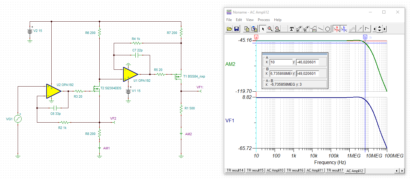
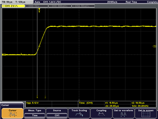
Using the EVM they find that the bandwidth is limited to 20kHz, even after removing some passive filtering components such as C3 and C4.

How should they proceed to get to the required 200kHz ?

Best regards

Ueli

---------------------------------

https://www.ti.com/tool/XTR111-2EVM

  • Hi Ueli,

    the bandwidth of the XTR111 is mainly dominated by the gate capacitance of external MOSFET. See section "Dynamic Performance" of datasheet.

    From figure 39 of datasheet you will also notice that the output signal is superimposed by switching noise from the internal chopper scheme. See also figure 6. The fundamental of this noise is 10kHz. You can also see the harmonics at 20kHz, 30kHz, and so on. A good remedy of decreasing this noise is to install a filter cap in parallel to the burden (load) resistance. 10nF times 500R gives a low pass filtering corner frequency of 32kHz. Even with this low pass filtering a 30mVpeak switching noise is superimposed to the output. 30mVpeak across 500R means a superimposed noise current 60µApeak.

    So, although the "naked" XTR111 offers a bandwidth of about 1MHz (see figure 3), because of output low pass filtering the final bandwidth is only 32kHz, which is usually fully sufficient for a standard 4...20mA application. And that the external MOSFET furtherly slows down the XTR111 a bit is no big mistake, usually.

    If you can live with the increased noise, you can remove the low pass filtering and try to take a MOSFET with low gate capacitance. See table 1 of datasheet. But keep in mind that the 10nF cap at the output may also be necessary to keep the output stable when connecting longer cables to the output. And the external current limit scheme also profits from this 10nF cap.

    Kai

  • Hi Kai

    Thank you for the quick and detailed reply !

    My understanding was also that the 4mA ... 20mA current loop interface is normally used for low bandwidth signals, often with long wiring where the current loop offers better immunity to interference compared to a voltage signal.

    I will check the use case details with the customer.

    Best regards

    Ueli

  • Thank you, Kai.

    Hi Ueli,

    Please let us know if you have additional questions.

    Thank you and Regards,

    Luis

  • Hello everyone,

    As Ueli mentioned, I'm having issues reaching 100kHz, even if the XTR111 datasheet gives the impression one should be able to reach 1MHz. I'm doing my tests on the XTR111EVM board where I removed the output filters to try to reach the bandwidth limit (even if paying in noise), and couldn't get beyond 20kHz. My application requires a bandwidth of 200kHz in the range 4-20mA (regardless of the bandwidth for typical 4-20mA applications). 

    Following the suggestions in the Dynamic Performance section, I replaced the MOSFET looking for smaller Cg, using, for example, BSP92P, BSP316P and BSS192. This worked well up to maybe 75kHz. I also added a class AB between the output of the XTR111 and the MOSFET gate which worked quite well with the original BSP170P up to, again, a maximum of around 70kHz, where I start to get distortion on the output. Similar results in terms of BW were obtained with a fast follower between the XTR111 and the BSP170P, but with quite some noise added. For the MOSFET replacements I tried to keep a good thermal dissipation, as some worst-case tests showed this component could warm up to 55C at room temperature, and my application requires it to be able to operate in 85C environments. So this discouraged me from taking much smaller packages, although for test purposes I could give them a try to see if we can gain more BW.

    In summary, I failed to see even 100kHz of BW. Would you have any suggestions on how to get at least 150 or 200kHz? 

    Thank you very much in advance.

    Patricio

  • Hi Patricio,

    there are still other methods to generate a 4...20mA current. The improved Howland current pump could be an alternative, for instance.

    Can you give some more details on your application? Is a cable connected to the output of current source? Do you need the current limiter? What is the exact load being connected to the current source?

    Kai

  • Hi Patricio,

    The XTR111 is optimal for relative low frequency 4-20mA current transmitter applications requiring DC accuracy. 

    The datasheet discusses the dependency of the XTR111 output current rise time on the gate capacitance of the FET on the "Dynamic Performance" section.  Because of the limitation of the large signal step response due to the gate capacitance, the device will not meet the 100-kHz signal requirement.  In addition, the accuracy of the XTR111 internal current mirror relies on the dynamic matching of multiple individual internal current sources resulting in some output glitch noise at 10kHz. The device is most often used with an RC filter at its output for relatively low bandwidth applications, where the corner frequency of the external RC filter is often less than 10kHz.  For example, the XTR111 is not optimal for HART modem applications, where the HART application has strict noise and frequency response requirements.

    As Kai has mentioned, the Howland current source or a different current source circuit will be required to meet the 100kHz requirement.  Attached is a couple of application notes that may be useful on the Howland current source.

    If you let us know the details of the application, (supply, load inductance/capacitance/resistance requirements, and noise/accuracy targets) we are happy to assist with other circuit suggestions.

    AN-1515 A Comprehensive Study of the Howland Current Pump

    'Improved' Howland current pump with buffer circuit

    Thank you and Regards,

    Luis

  • Hi Patricio,

    here comes a somewhat faster 4...20mA current source:

    patricio_opa192.TSC

    Kai

  • Hello Kai, 

    Thank you for your reply. In our application the MOS current output goes directly to the device's output connector, from where a cable of around 3m drives the current to a burden resistor, of around 200 ohms. The cable must be properly chosen to make sure we don't introduce undesired LC parasitic components. In any case, for the tests I was doing now I was using the Rl (249 ohms) on the XTR111EVM board, so "ideal" conditions. The current limiter is not needed but doesn't hurt. Our application in principle shouldn't be able to demand more than 21mA from the XTR111. 

    I understand that this trans-impedance amplifier can be designed in a more discrete way and I thank you for your suggestion, but I was hoping the XTR111 could fulfil our requirements. I now finished my tests with different output MOSFETs and they all converge to a max of around 70, 75kHz. I might indeed need to look for a different solution. 

    Thank you, 

    Patricio

  • Hi Patricio,

    I have one last idea: The frequency response given in figure 3 of datasheet of XTR111 could be the small signal bandwidth. So you would need to check the bandwidth of XTR111 with a very small AC signal.

    Can you please check the bandwidth again by applying a sine wave input signal in the 1...10mV range being superimposed by a DC voltage of 2.4V to the Vin pin, while Rset is set to 2k? If the 1...10mV is too small, at least take an AC input signal which is as small as possible.

    By the way, what is the supply voltage of your XTR111 during the test?

    And have you already checked the speed with a fresh XTR111?

    Kai

  • Hi Kai, 

    I'm using 24VDC for the input PSU. For the input signal I was using a 3Vpp sine with a 2.5VDC offset.

    I can try your suggestion of the small signal AC and i'll try it too on a brand new XTR111EVM board. 

    Cheers,

    Patricio

  • So I tried with a fresh board and also with small signal but I got the same results :(

  • Hello Patricio,

    In terms of the large step signal slew response, the EVM is limited by the gate capacitance.  The datasheet specifies a rise time of typically about ~11μs with CGATE=130pF load.

    In addition, there is a 10nF load capacitance at the drain, and a couple of protection diodes that may add some load capacitance.  On a quick EVM measurement, with this transistor, without modifying the EVM board,  I measure about 26us current output rise time for a 0-5V output on RLOAD=2kΩ (0-2.5mA).

    The Slew Rate measured 0-2.5mA was around 26µs and the noise around 125mVpp. 

    The XTR111EVM uses the external PFET ZXMP6A13FTA with typical Gate Capacitance: CGATE  = 219pF. (This capacitance may vary and could be larger)

    A rough estimate the best typical case scenario Slew based on CGATE  = 219pF:

    Slew Rate (estimate) = (219pF / 130pF)* 11µs > ~19µs 

    I went ahead and Removed Cload=10nF , and protection diodes to improve slew rate; slew rate improved to about 20µs which is  relatively close to the estimate above.  I have not measured the small-signal bandwidth.

    Regarding the discrete high-side current source, similar to Kai suggestion, there is a high-side current source design procedure documented on the application note below.  The application note example uses a low voltage amplifiers, but as shown, could be modified to use a 36V precision amplifier such as the OPA2192 or OPA2197 (both of them are 10-MHz, 36V amplifiers) that can work with 24V.

    High-Side Voltage-to-Current (V-I) Converter - Texas Instruments

    In addition, attached is also a ppt file of a similar design I performed one year ago using the OPA2197 (or OPA2192) for a High-Side current source for a Customer, this design can be customized per your needs.  The simulated rise time was about 1.8 us for this design. The OPA2192 offers better offset drift/precision performance, but AC / slew rate performance is the same on these amplifiers, so you can use either one of these amplifiers.  The TINA simulation files are embedded in the power point file.

    Thank you and Regards,

    Luis

    High_side_V-I_Converter_OPA2197forum.pptx 

  • Hello Luis, 

    Thank you so much for the detailed response. Indeed, I had done similarly during my tests, removing diodes, protections and other accessories that could limit the bandwidth either at the input or output paths. I can confirm your results. I had tested few different MOSFETs and also introducing an AB class stage between the XTR111 and the MOSFET's gate. The AB class stage showed great results with the BSP170P extending the bandwidth up to at least 65kHz. However I prefer to keep the design as simple as possible and reduce external components (which was the main goal of using the XTR111) avoiding the use of the AB stage, which was there just to prove that it was indeed possible to reach that BW. A good replacement part was BSP92P with which I reached 75kHz without any output distortion and no further undesired effects, such as heat, noise, etc. In any case, trying different combinations of parts and tricks I didn't manage to reach not even 100kHz, so the XTR111 won't be chosen for this application. 

    Thank you very much for the additional material, specially the simulation files, which I'll be diving into during the next days. 

    Regards,

    Patricio

  • HI Patricio,

    Thank you, this makes sense.  Please let us know if you need anything,

    Kind Regards,

    Luis