This thread has been locked.

If you have a related question, please click the "Ask a related question" button in the top right corner. The newly created question will be automatically linked to this question.

THS4631DDAEVM: Not working as expected from TINA

Genius 14729 points
Part Number: THS4631DDAEVM
Other Parts Discussed in Thread: THS4631DGNEVM, TINA-TI, THS4631

Hi Experts,

We have here issues regarding THS4631DDAEVM.

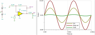
"I am using THS4631DGNEVM as a non-inverting amplifier with a gain of 2. I am sending a -5V to +5V signal which will be amplified to -10+10V. However, I am not seeing a gain for 2 for the input signal. I have a schematic and TINA-TI simulation of my setup I can provide

The simulation shows the setup for amplifying a -5V to 5V sine wave. I would also like to amplify a 0V to 10V sine wave signal. For this, I set the supply voltages to +25V and -5V. However, for both scenarios I am unable to double the amplitude. I was under the assumption this device has a gain of 2 as supplied.

Also, for the non-inverting setup, I usually connect the J1 pin to earth ground and the input signal to J2. However, If I try an inverting setup and ground J2 and connect my input signal to J1, I get a large current draw through J1. Is this normal or a symptom of a short / bad board?"

Thank you.

Regards,
Archie A.

TINA: 0535.THS4631.TSC

  • Update:

    Able to verify with the customer if the EVM was set-up the same way as it shows from page 19 of its D/S. And check the R1 resistor as it may damaged when he conducted the inverting setup. Tried asking scope for Input/Output waveform. Below is their response:

    "I have confirmed that the EVM is connected as on page 19. I have checked the input and output signals using an oscilloscope. The input impedance from the function generator that provides the input signal is set to 50 Ohms and the impedance of the oscilloscope was set to 50 Ohms as well. I also confirmed I have J1 pin grounded. "

    Further assistance please.

    Thank you.

    Regards,
    Archie A.

  • Hi Archie,

    I would definitely check R1. Also the Z3 series 950 Ohms might be causing some output attenuation depending on the load termination with respect to ground. See if they are getting the right swing when probing directly at the amplifier output pin.

    Best,

    Sam

  • This is what I mean:

    Best,
    Sam

  • Hi Sam,

    Thanks for this representation. I didn't notice the Z3 there, combined with such load impedance (50 ohm) termination really causing it to attenuate.

    Will check this out with the customer.

    Regards,
    Archie A.

  • Hi Archie,

    Sounds good. Please let me know if they continue to have issues.

    Best,

    Sam