


Other Parts Discussed in Thread: INA181
Hi Expert,
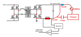
My customer is using INA181-Q1 in their OBC project. The INA181-Q1 is put on the secondary side of OBC. You can find the system block diagram as below.
In customer's use-case, they will perform the 1500Vac voltage pressure test on chassis after board assembly. The detailed procedure describe as below.
- The Y-cap is placed between HV_GND and chassis
- Short Vhv_bat to HV_GND
- Add 1500Vac between Vhv_bat and chassis.
Does INA181-Q1 suitable for this use-case? Does it have any risks for INA181-Q1?
Thanks!
Ethan Wen
