This thread has been locked.

If you have a related question, please click the "Ask a related question" button in the top right corner. The newly created question will be automatically linked to this question.

OPA2211A: Sourcing current from the input pins

Part Number: OPA2211A
Other Parts Discussed in Thread: OPA211, OPA196, OPA197, OPA191, OPA192

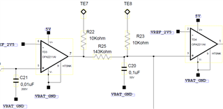
For a cascaded comparator application, we use two OPA2211 OP-AMPS as output of one is connected to input of another over a 143kOhm resistor. The partial schematic of the circuit is attached. However, when the primary output is pulled to low, the input of the secondary OP-AMP cannot be zero due to the current sourced by the secondary OP-AMP. the resistor is by-passed over a current measuring multimeter and the sourced current measured to be higher than pin source/sink limits. I cannot find detailed information for this case in the datasheet. Can you provide me with the input structure of the OPA2211 and the mechanism for this current sourcing? 

  • Murat,

    You seem to configure the OPA2211 op amps in the open-loop configuration (with no negative feedback), which inherently will lead to inputs being pulled apart resulting in large input current due to turning-on of the back-to-back input protection diodes - see below.  Op amp should NOT be used without negative feedback. If you need further assistance, we need to see the entire schematic.

  • Hello Murat,

    We can't provide detailed information about the OPA2211 input circuit design. The information is company proprietary. I'll share general information about the OPA2211 with you.

    The OPA2211 is a highly precision op amp and I find it an unusual choice for a single-supply comparator application. It is not a rail-to-rail input or output op amp and if the input voltage falls outside the Common-mode voltage (Vcm) input range of (V–) + 1.8 V to (V+) – 1.4 V, then a common mode violation occurs and the input electrical behaviors are not defined. Additionally, in datasheet section 8.1.2 - Input Protection, it states "The input terminals of the OPA211 are protected from excessive differential voltage with back-to-back diodes, as shown in Figure 44." Applying an input voltage differential to the op amp that approaches or exceeds the forward voltage of a clamp diode can cause significant input current flow from the circuit's VREF_2V5 to the input source.

    Lastly, the OPA2211 uses input bias current cancellation to reduce the input bias current required by the input bipolar transistors. The polarity can be either positive, or negative depending on how the input bias current was adjusted and minimized during manufacturing of the op amp. The bias cancellation circuit connected at the input transistor base has the ability to sink, or source current. How this source behaves when forced into non-linear operation is not characterized because that is not an expected operating mode for the op amp.

    Other op amps such as TI's OPA19x series, OPA191, OPA192, OPA196, OPA197, etc. are rail-to-rail input op amps and they don't use input clamps. They actually make a higher performing comparator than most op amps.

    Regards, Thomas

    Precision Amplifiers Applications Engineering

  • Hello Thomas,

    Thanks for your answer. I actually know OPA2211 is overclassified for a single-supply comparator application. However, the single-sided supply acceptance and rail-to-rail output capabilities with ease of reaching at my situtation (due to the chip crisis, I preferred to use available components at our shelves) led me to choose this part number. After you warned me about the input overvoltage protection, I found out the problem source and eventually eliminated this part number for this application. Thanks for your help.