This thread has been locked.

If you have a related question, please click the "Ask a related question" button in the top right corner. The newly created question will be automatically linked to this question.

INA213: Continuation from [INA213: TIDU357A total system error]

Part Number: INA213

Hi Support Team,

I have some questions about TIDU357A and this is continuation from below thread.

https://e2e.ti.com/support/amplifiers-group/amplifiers-internal/f/amplifiers-internal-forum/1085377/ina213-tidu357a-total-system-error?tisearch=e2e-sitesearch&keymatch=TIDU357A#

(1-1) Could you please tell me what Vs_INA_spec and Vs_INA_sys on page 22 indicate?

(1-2) Could you explain the idea of how to calculate EIna_psrr? 

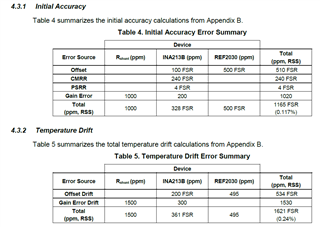
(2) Is it correct to think that all the errors used in Tables 4 and 5 on page 10 are standard deviations? 

Thank you for your help.

Best Regards,

Taito Takemura

  • Hi Taito,

    "Vs_INA_spec = 5V" means that the input offset voltage of INA213 is specified at a supply voltage of 5V. "s" stands for the supply voltage.

    "Vs_INA_sys = 3V" means that the INA213 is not supplied by 5V in this circuit but by 3V.

    As consequence the shift of supply voltage from 5V to 3V causes a shift of input offset voltage, expressed by the power supply voltage rejection (PSRR). The PSRR calculates how much the input offset voltage changes when reducing the supply voltage from 5V to 3V.

    And the idea of "EINA_Vos" is to put the input offset voltage (5µV) in relation to the maximum shunt signal voltage (50mV) to change from absolue error values to relative error values. 5µV is 0.01% or 100ppm of 50mV, according to

    5µV / 50mV = 0.0001 = 0.01% = 100ppm

    When errors have to be added it may be simpler to change from absolute errors to relative errors.

    Kai

  • Kaito, Kais explanation upstairs is spot on for everything. Please let me know if you have any questions regarding his answer. 

    Regarding your last question as to standard deviation, I believe the comment Guang made in the previous post is that the RSS of these values is a standard deviation of error for the totality of the response. Typically, for these types of analyses, we look at the worst case error before applying RSS analysis, which would not be based on statistics, but via test criterion given in the datasheet. In short, it would be my opinion that the totals listed in Tables 4&5 are standard deviations as per Guang's original post, but the individual parameters would be based on worst case contributions. 

  • Hi Carolous, Kai,

    Thank you for your answer. I have one question I would like to ask.

    I think the equation (8) to be an error adjustment when the power supply voltage is different from the data sheet.

    However when Vs_INA_spec = Vs_INA_sys, the values of EINA_PSRR and EINACMRR will be zero. This will eliminate the error component of PSRR and CMRR.
    I think the values should follow Vos_ina_psrr and Vos_ina_cmrr, respectively even when  Vs_INA_spec = Vs_INA_sys.

    Could you please tell me why is it like this, how to think the PSRR and CMRRerror when Vs_INA_spec = Vs_INA_sys?

    Best Regards,

    Taito Takemura

  • Takemura-san,

    Equation 8 is simply the calculation of error in the system between the measured value and the calculated ideal. This follows the standard error formula to calculate this value.

    Your understanding that CMRR and PSRR values will contribute zero when Vs_INA_spec = Vs_INA_sys is correct. This is because the points outlined in the datasheet are where the device is calibrated by design to operate most efficiently. If the customer in fact uses the device at Vs = 5V, and Vcm = 12V, contributions to the error equation from PSRR and CMRR would be zero.