This thread has been locked.

If you have a related question, please click the "Ask a related question" button in the top right corner. The newly created question will be automatically linked to this question.

INA827: 1 gram not equaling 1 gram when measuring with loadcell

Part Number: INA827
Other Parts Discussed in Thread: OPA330

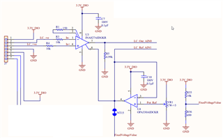
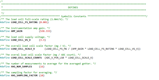
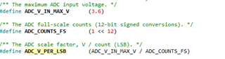
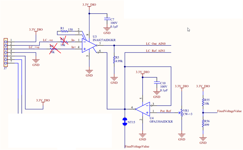
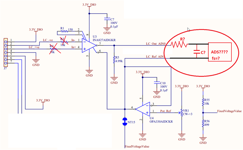
I am using the INA827 to drive a 5kg FMZK loadcell. And despite thinking we have the equations calculated correctly and our resistors set etc we are not seeing an accurate reading on the loadcell. Our loadcell readings are about 15-20% below what our known weight values are and we have + or - 10g variance as well.. I am attaching the schematic from our PCB to this post and the C code we we are using in conjunciton. Any help is greatly appreciated as this is really stalling our project ATM .

  • Assuming you properly null the output voltage offset with OPA330 and account for any DC voltage and error left at INA827 REF pin (e.g. Vos=+/-50uV), there are couple of other things that may contribute to the reading error. 

    1. There should be no input resistors in series with input terminals of INA827 as they will causes additional error due to input bias current (95nA*10k) and current noise.  If you added them for overvoltage protection, please minimize their value so the maximum input current is 10mA.

    2.  What is the sampling frequency of your measurement?  In the gain of G=538, the INA827 bandwidth is only about ~20kHz and settling time of around 100us - see below. Thus, please make sure your sampling frequency is below 10kHz or you'll be measuring an unsettled value.

    3. Because of the high gain, the input voltage and current noise may play a major role and thus you need to increase the averaging from 16 to at least 100 times.

  • Hi Matthew,

    does the loadcell work with a bridge voltage of 3.3V? And are you sure that you have the right scaling factor for the loadcell?

    Also, are you sure that the observed variance is not caused by the unavoidable hysteresis of loadcell?

    Can you give a link to the loadcell?

    What ADC are you using? What is the sample rate? Do you use a charge kickback filter?

    Kai

  • I think you average the output readings taken with multimeter but if you use ADS what R/C filtering scheme do you employ?

  • We are not using any R/C filtering scheme, those 2 pins go directly into the ADC on our Nordic nrf52840. 

  • Hi Kai, I am not sure if the loadcell works with a bridge voltage. No I am not certain we have the correct scaling factor, I was hoping you could tell me that with the circuit and code. 

    I could see the fluctuations from 1 measurement to the next being hysteresis, but we are linearly about 20% off our measurements, we are cutting cans of food and they actually weigh 172g and the load cell reports them as 140-150g typically.

    Micro Lightweight Load Cell Sensor 2kg 5kg 10kg (forsentek.com)

    We are using Nordics NRF52 series on board 12 bit configured SAADC. We actually use a REALLY low sample rate, we clock at our system clock 10 ms or 100Hz. The capture time is 10us which is the Nordic default. I am not certain about a kickback filter the schematic I provided feeds directly into our to analog input pins on the Nordic chip

  • Matthew,

    Our support team mostly deals with hardware related questions and not software, which actually should be directed to Nordics NRF52 manufacturer.  Having said that, looking at the nRF52840, it is a controller with a basic eight channels for single-ended inputs or four channels for differential inputs 12-Bit SAR ADC.  These are relatively low resolution low precision compared to TI's Precision ADCs and Delta-sigma’s converters. 

    Precision SARs may require an RC charge kickback filter but in this case the 12-bit ADC appears to be low resolution and sampling rate is slow. However, a filter between ADC and INA can still be helpful to limit broadband noise.   The ADC datasheet does not recommend a specific RC filter.  In many bridge applications we often recommend a differential R-C-R filter at the inputs of the instrumentation amplifier, using a larger 10x differential input capacitor and 1x common-mode capacitors.  The filter BW can be set relatively low in the 100’s of Hz since weight-scales are essentially very low frequency or slow moving signals and you claim it samples signal at 100Hz.

    All in all, we would recommend a filter with relatively low frequency at the instrumentation amplifier inputs using the 10x differential and 1x common-mode capacitors to reduce extrinsic noise, and ‘maybe’ a higher bandwidth (on the few kHz) optional RC between the INA and ADC to reduce any INA broadband noise.  In many cases, the bridge sensor noise is dominated by 60-Hz (or 50-Hz) line-noise.   Delta-sigma converters for weight scale applications incorporate digital filters with attenuation notches at 60Hz or 50-Hz.  In this case,  since this is a SAR ADC that does not incorporate a digital filter, one can average samples during a complete 60-Hz (or 50-Hz) line cycle to eliminate the line noise.  For example, sample at 600SPS, and average 10-samples to eliminate the 60-Hz noise.

    In high precision/high resolution bridge applications, we tend to recommend a ratiometric configuration, where the same voltage source is used to bias/excite the bridge, and the same source is used to generate the ADC reference.  Performing sensor measurements in the ratiometric configuration provides a significant advantage, since the same low frequency noise and drift errors are proportionally reflected at the ADC inputs and at the ADC reference inputs.  Errors due to the absolute excitation low frequency noise and drift; and reference low frequency noise are virtually eliminated since they are seen equally proportional at the ADC input and reference input, and will tend to cancel.

    For any additional questions, I will refer you to Luis, our factory ADS drive expert, that can better address any remaining issues with your application. 

  • Thank you for your all your help Marek

  • Hi Matthew,

    172g would result in an output voltage of INA827 of 61.1mV and 140g in 49.7mV, relative to the REF pin potential of INA827 and after subtracting the offset voltages of Loadcell and INA827. Am I right?

    Do you see this voltage at the output of INA827 with a voltmeter (DVM)?

    Take care, don't directly connect the voltmeter to the output pins of INA827 and OPA330 but insert isolation resistors of some hundreds of Ohm into each line first. Mount the isolation resistors directly at the output pins. Also, remove the connection to the ADC for this test.

    If not, I would check the combination of loadcell and INA827 separately first:

    Disconnect anything from the INA827 (the loadcell excluded). Supply the INA847 with +/-15V and connect the REF pin to signal ground. Supply the loadcell with 3.3V. Short-circuit R3 and R4, as recommended by Marek.

    Do you now see the proper output voltage?

    If not, take a fresh INA827 and a fresh 150R resistor and try again.

    If there are still issues, the wrongdoer very probably is the loadcell and not the INA827.

    Divide and conquer!

    Kai

  • Thank you Kai, I have passed your recommendations along to my teams PCB specialist. If I can get them to run this test I will follow up with the results. I really appreciate both yours and Marek's help and expediency in responding to my situation.

  • Thank you Matthew,

    We will wait for the results,

    Best Regards,

    Luis