This thread has been locked.

If you have a related question, please click the "Ask a related question" button in the top right corner. The newly created question will be automatically linked to this question.

TLV522: Signal excursions in TLV522 PIR circuit

Part Number: TLV522
Other Parts Discussed in Thread: TPS63900

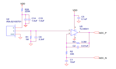
Hi I'm using a circuit very similar to the one below. U5 is a TLV522 (half), U2 is a D203s standard PIR sensor. The output is fed into a differential input ADC (uC).

The problem is that the output signal shows slow excursions (multi-second) of multiple mV's on the output around the zero point. I.e. when the PIR is covered, there still is signal, but it does not seem to be noise.

The amplifier does stabilize on the bias (DC) voltage of the PIR sensor, but seems to wander (oscillate?) around it sometimes.

It does not seem to be completely stable somehow. Have been playing around with the values C1/C2/R2/R3, but I don't seem to get things right. I recall a former build where this circuit performed really well. Am I overlooking something? Are oscillations possible in such circuit, or should it be inherently stable?

  • Hi Rogier,

    there are several options you can try:

    1. Remove C9.

    2. Heavily increase C14.

    3. Add an isolation resistor of 10...47k in series to the output of U5.

    What is supplying the TLV522? A Coin cell?

    Does it work when you completely remove the ADC from the TLV522?

    This thread may interest you:

    https://e2e.ti.com/support/amplifiers-group/amplifiers/f/amplifiers-forum/1124716/tlv8544-detection-error-increase-when-supply-voltage-drops

    Kai

  • Hi Kai,

    Thanks for your feed back. I actually shared a reference design, because I did not want to colour the question too much. The actual circuit looks like below, but during testing/fiddling/getting things work I've tried numerous different values of key components. I also tried the design without the U6B follower stage. (I designed in the follower because I had one spare Op-Amp left anyway, so I figured: give it something to do and get it in a known operational state...)

    The ADC shows a 2.5pF (max) capacitance on its inputs, so low that I figured that it would not impact the driving OpAmp too much. The ADC is sampled only few times (3-10Hz) a second. I also tried adding 100Ohm series resistors, but will try with much larger values.

    The power supply of the PIR is very well decoupled, and includes a 220uF (low leakage) electrolytic, a diode and some more R/C low pass. Also the forum post you shared (thanks) mentioning the voltage droop problems, I don't really have this problem in this design, but still I stop the ADC sampling for some time around power surges (i.e. when using the LoRa radio), in order to suppress any spurious signal/triggering from that.

    The power of the design comes from two LiSOCl2 batteries (AA) and a TPS63900 buck/boost supply. I will try to power the PIR sensor directly out of a battery, but I don't think the power is a problem here. It's just that sometimes (i.e. once every say 20-30 seconds) the signal just takes "a walk in the park", very slow signal, multiple seconds before to come back to base. Could it be there's some sub-1Hz oscillations going on somehow?

  • Hi Rogier,

    a capacitive load at the output or PIR presents a short-circuit to signal ground and can destabilize the FET circuit in the PIR. Why not using a series resistor in front of C3? Or why not omitting C3 completely?

    I would remove R6. I don't see any advantage of using a two stage low pass filter, if C7+C8 are much smaller than C2. You merely isolate C2 from the PIR by R6.

    I would remove anything from C6. Nano-OPAmps are really critical and show no good phase margin. So I would avoid any manipulations in the feedback path. Why not connecting C29 with a suited series resistance directly to the output of PIR?

    Nano-OPAmps have very low phase margins even without any capacitive load. So I would use an isolation resistor at the output of OPAmp and make it as big as possible. Some Nano-OPAmps need especially high isolation resistors at rather small load capacitances, not at higher load capacitances. You may want to carry out a phase stability analysis to see what isolation resistor will be sufficient.

    Take care, the input capacitance of a voltmeter (DVM) or the scope probe capacitance can fully destabilize a Nano-OPAmp. So never touch any pin directly without isolation resistor.

    Take care, Nano-OPAmps are no usual OPAmps but can be very tricky. In order to make the current consumption ultra low the internal circuit uses tricks which can make issues.

    Also take care that the supply voltage from the DC/DC switcher is absolutely clean, stable and noise-free. A Nano-OPAmp has very limited abilities to suppress supply voltage noise. So please use state-of-the-art low pass filtering at the input and output of DC/DC switcher. Pi-filters are preferred.

    Kai

  • Hi Kai,

    Thanks again for your insights. Especially the remarks on the specificity of Nano-power opamps makes sense to me. I just assumed this to be a low-power device with (just) a very low BW-gain product. Apparently there's more to it. I have a much more stable system now by changing R21 to a 20kOhm value and including a 20kOhm series resistor to the output of U6A as well.

    As far as the power supply is concerned, would it be a good idea to also power the Opamp from the 'PIRPOWER' rail (i.e. high-ohmic/low current but probably pretty clean)?

    I'm considering implementing a FIR hi-pass filter (DC bias blocking) in software on the PIR sampling, in order to eliminate the need for a 'PIRRef' input (and differential ADC) altogether.

    Thanks again for your insights on this topic!

  • Hi Rogier,

    I have a much more stable system now by changing R21 to a 20kOhm value and including a 20kOhm series resistor to the output of U6A as well.

    This sounds good Relaxed

    As far as the power supply is concerned, would it be a good idea to also power the Opamp from the 'PIRPOWER' rail (i.e. high-ohmic/low current but probably pretty clean)?

    You could give it a try, provided the voltage drop across R4 isn't too high.

    But I would prefer to spend the OPAmp a separate RC low pass filter in its supply voltage line. A 100R resistor and a 10µF cap could do the job.

    Kai