This thread has been locked.

If you have a related question, please click the "Ask a related question" button in the top right corner. The newly created question will be automatically linked to this question.

OPA277: If there have some the solution to absorbs the glitch from OP-amps by NPN and resistor?

Part Number: OPA277
Other Parts Discussed in Thread: DAC8760, TMUX1248, TMUX7236, TMUX6236, OPA188

Hi everyone,

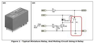
How to clamp the output voltage of OPAmps to signal ground by the help of a switch whenever the supply voltage falls under a certain level? How to use the resistor in series to the output of OPAmp that limit the current through the clamping switch. Could you give me some  advices or diagram to solve it?

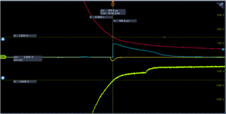
Background: There have the glitch when the OPA277 was power down. Scope as follow:

the red line and green line are the VCC and VEE of OPA 277, and the yellow line is the DAC8760 Vout, and the blue line is the Vout of OPA277.

  • Hi Hao,

    the awesome Mr. Rod Elliott shows -better than I can- some ways to accomplish this:

    https://sound-au.com/articles/muting.html

    Kai

  • Hello Hao,

    As you can see from the circuits shown in the link Kai provided all the circuits are quite involved. One configuration may prove to have more acceptable performance with a particular circuit and op amp than another. As Mr. Elliot discusses the op amp needs to be tolerant of having its output shorted. The OPA277 is tolerant of an output short to ground in a dual power supply configuration.

    The "mute" signal in this case could come from the output of a comparator that is sensing the supply line voltage. When the voltage drops below a certain level the comparator output would change state, turn on the output switch and effectively short the OPA277 output to ground.

    When an op amp having an enable/shutdown is placed in output shutdown mode the output becomes a very high impedance. It is then unable to provide any appreciable output current. Tests made some years ago by the Precision Amplifiers App's team verified that some CMOS op amps present a very high output impedance in shutdown mode. Applying the supply voltage sense comparator concept to their enable/shutdown function might be a less complex option.

    Regards, Thomas

    Precision Amplifiers Applications Engineering

  • Hi Kai

    Thank you for link.

    But I have a question about the relay switch from the fig1. What is the difference between switch to no and NC before and after relay power up?  They all seem to be connected to the earth( GND). 

    Best.

  • Sorry, I understand the circuit output GND normally and output audio signal when the relay is working on, right? 

  • I still have a question that why don't we just use a analog switch such as TMUX1248 to replace the relay directly?

  • Hi Hao,

    Sorry, I understand the circuit output GND normally and output audio signal when the relay is working on, right?

    Correct.

    I still have a question that why don't we just use a analog switch such as TMUX1248 to replace the relay directly?

    Ron Elliott's article discusses "muting circuits for audio", as the title says, and in audio circuits you usually want a high degree of muting. Because of that the ON-resistance should be very small. A good audio relay presents an ON-resistance in the milliOhm range while your TMUX1248 has an ON-resistance of about 3R.

    But in your application the ON-resistance should not play a relevant role as you only want to suppress the glitch a bit? In this case you can use an analog switch instead of the relais, of course. Increase R1 to 1...2k to get sufficient dampening and to not overload the output of OPA277, as Thomas already mentioned.

    But take care, the analog switch must be able to withstand the output voltage of OPA277. So, if the OPA277 is powered by +/-15V, as an example, the analog switch should also be supplied with +/-15V. Keep in mind that the TMUX1248 only withstands +5V.

    Kai

  • Thanks for your reply and I get it.

  • Hi Hao,

    The analog multiplexer placed at the OPA277 output looks like a good approach that can provide a low output resistance to ground when a supply under-voltage occurrence is sensed. 

    Kai brings up a good point about the useful voltage range for the TMUX1248 being limited to +5 V. Since the OPA277 is commonly applied in higher supply voltage applications often using +/-15 V, a higher voltage MUX might be needed. I did a search on TI's higher voltage SPDT MUX products and the TMUX6236 and TMUX7236 could be good options:

    https://www.ti.com/product/TMUX6236

    https://www.ti.com/product/TMUX7236

    Regards, Thomas

    Precision Amplifiers Applications Engineering

  • Hi Thomas,

    Thanks for you advice. I'll try it soon. Grinning~

    Best regards, Hao.

  • Hi Thomas and Kai,

    I just know that customers don't have PD glitch issues when using the OPA188, why does the OPA277 have a glitch issue and the OPA188 have not?

    Hao

  • Hi Hao,

    can be pure coincidence. I wouldn't count on it.

    Kai

  • Hello Hoa,

    I see you have started a new and separate on the OPA188 and OPA277 output glitch issue. I am going to close this one now.

    Regards, Thomas

    Precision Amplifiers Applications Engineering