- Ask a related questionWhat is a related question?A related question is a question created from another question. When the related question is created, it will be automatically linked to the original question.
Hi Team,
I have a question regarding the OPA541P
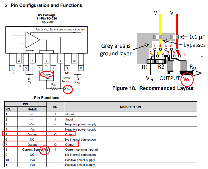
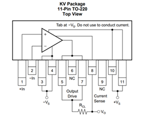
In TI data sheet, it shows:
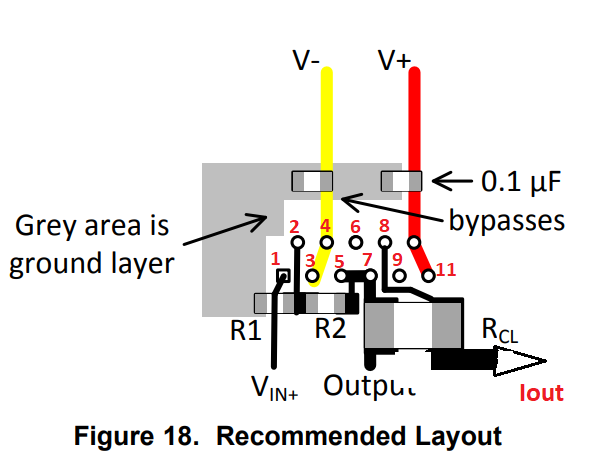
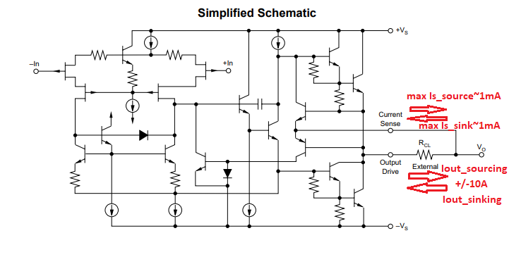
It seems that the current limit resistor will be connected between pin 5&7 and Pin 8. The output to external load will be at pin 8. Pin 8 is probably just a sense line that can sense the voltage across Rcl and determine if it should shut the device down. Current should flow out from pin 5&7 through the Rcl to the external load that is at Pin 8.
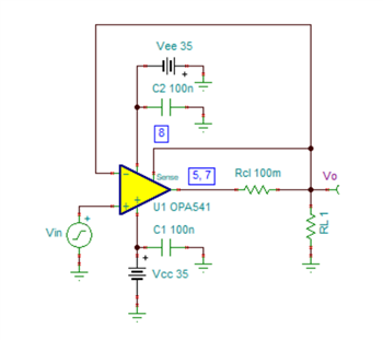
However, another figure shows different:
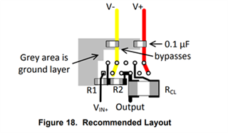
The above shows that the output top external load with be from Pin 5&7.
Which one is the right one. I had a feeling Figure 18 is wrong. With the above figure, there will be no current flow through Rcl.
Thanks!
Connor