This thread has been locked.

If you have a related question, please click the "Ask a related question" button in the top right corner. The newly created question will be automatically linked to this question.

AMC1200: Schematic Review for Voltage measurement using AMC1200

Part Number: AMC1200

Hello , I am planning to use AMC1200 in voltage measurement , there are going to be 2 different ranges 1000Vpeak range and 100Vpeak range.

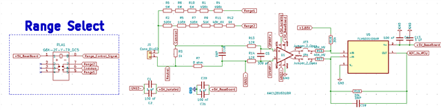
A relay is used to switch voltage divider branches in order to switch between ranges.

The schematic for the voltage measurement section is shown in the following figure , I 've used TIDA000555 from texas instruments as reference design.

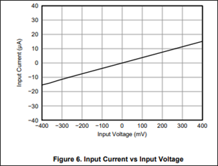
The AMC1200 input is going to be +/-250mV for both ranges so it's output will be 4V p-p which is then signal conditioned to be from 0 to 3.3V around 1.65V offset

Any opinions or comments on the schematic? 

Thank you very much in advance.

  • Hi Amr,

    Interesting to see a similar approach for the voltage measurements! This schematic looks good! 

    R? connected to the negative input and sensing resistor should not be necessary for the AMC1200. It has a switched capacitor input structure and the input bias current is linear with respect to the voltage applied to the input. 

    Remember to add an RC/chargebucket at the output of the single ended conversion. For optimal common-mode noise rejection, I also recommend performing the differential to single-ended conversion as close to the MCU ADC as possible. 

  • Thank you very much for your kind words and useful info

    Should I add this 1 nF cap between the isolated GND and the non-isolated ground same as this design?

  • Hi Amr,

    Will you be testing this design for EMI performance? CISPR11 or CISPR32 is common for medical and industrial designs, CISPR25 for automotive. 

    If not, then I don't think this will be necessary, at least for the AMC1200. You may want to consult other device datasheets to see if it is mentioned. If yes, then you may want to include placeholder(s) in the schematic and layout. 

    Capacitors spanning the isolation barrier are used to provide a return path for the energy crossing the barrier. The energy is attempting to return to it's source, but is unable to and radiates from the traces and planes on either side of the isolation barrier: similar to a dipole antenna. The value of the capacitor will determine the frequency range of effective EMI attenuation. It is also very important to ensure that the voltage rating of the capacitor spanning the barrier is as high as the isolation requirement. Several capacitors in series can be used if necessary. 

  • I will not test the board for EMI , thank you very much in advance, May you Please keep this thread open for short period till I send the files for fabrication in case I Have more related questions?

  • Sure thing Amr, please let me know how fabrication and testing goes. I'm very interested to see results for the current sensing board. 

    The thread should not lock automatically for a few days. If it does, please start a new thread and link to this one in the post.