This thread has been locked.

If you have a related question, please click the "Ask a related question" button in the top right corner. The newly created question will be automatically linked to this question.

OPA2180: OPA2180IDR

Part Number: OPA2180
Other Parts Discussed in Thread: OPA180, OPA196, OPA197, OPA191, OPA192, TINA-TI

Hi,

Good day!!

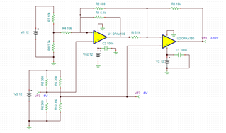
As part of one of our design We are using the OPAMP "OPA2180IDR" as Single supply Strain Gauge Bridge Amplifier Circuit. The Output of this Opamp is Connected to the ADC "ADS1220IRVAT" .
The Simulation file is attached Below.


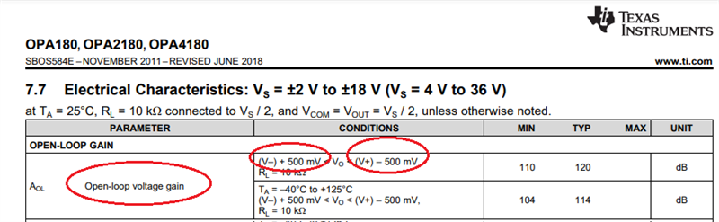
In the application note

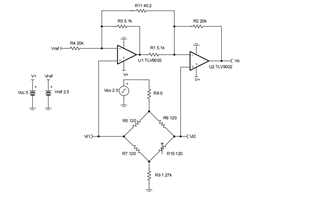
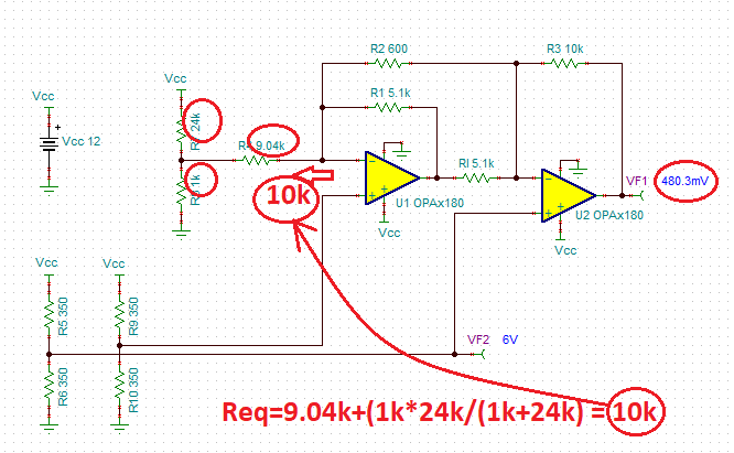
We have replaced the resistors as mentioned below,

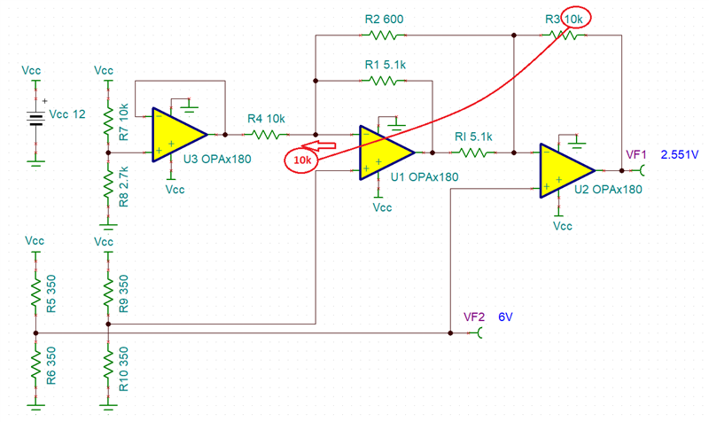
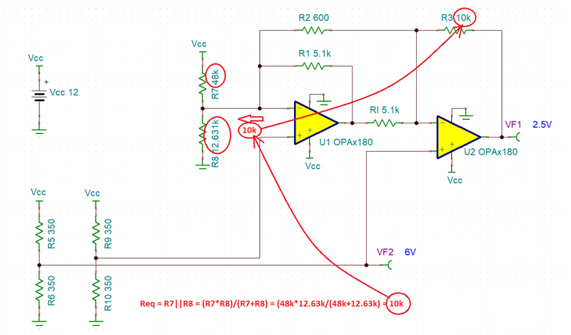
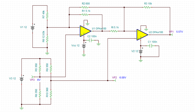
R11:600 Ohm, R4: 10K, R2: 10K
In our case,
The excitation voltage of the strain gauge is 12V.
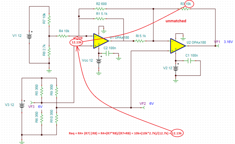
The reference volatge is set from a voltage divider using resistors 10K and 2.7K and the reference voltage (2.551V) is taken accross the 2.7K resistor.
The bridge resiatance is 350 Ohms and the output of the strain gauge is 2mV/V.

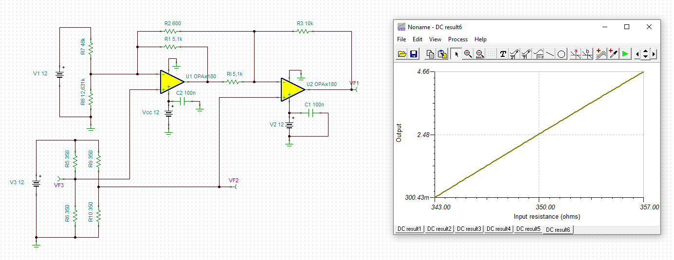
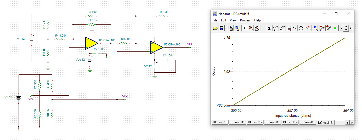
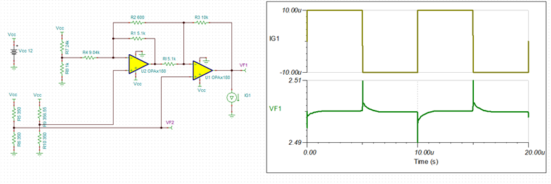
Below is the response of the ADC when force is applied.


The output voltage of the circuit seems not linear with the applied force.
A sudden voltage dip occurs while measuring the voltage as shown in the graph. May i know the reason for that?

Kindly let me know whether this circuit is stable/ Not. What changes i need to do inorder to avoid this Voltage dip and to maintain linearity with the Applied Force?

  • Hi Alan,

    there's a mistake in your circuit: R3 should equal R4. But the voltage divider R7 / R8 is ruining this symmetry. Either drive R4 by a low ohmic source or modify the resistors in a way that the -input of U1 sees a 10k source resistance.

    Kai

  • Alan,

    As Kai mentioned for the application to work as intended, R3 and R4 must match but they do NOT - see below.

    Thus, you either have to buffer the reference voltage as shown below

    or you need to set the reference voltage with equivalent resistors equal to 10k - see below.

    Having said that, OPA180 is a chopper amplifier where large unmatched input impedances may result in commutation of the input current (IB) spike (coming from the auto-calibration input switches) into an additional offset voltage error - for this reason I would recommend for this application linear op amps like OPA191 or OPA196 (GBW of 2.5MHz) and if the settling time is important please use OPA192 or OPA197 (GBW of 10MHz).

    In the future, for the sake of efficiency please attached your Tina-TI schematic - I have attached mine below.

    Alan OPA2180 Strain Gauge Bridge with Buf Ref.TSCAlan OPA2180 Strain Gauge Bridge with no Buff.TSC

  • HI Kai and Marek,

    Good Day,

    Couple of Doubts are there,

    1. Can we use instrumentation amplifier instead?

    2. Our ADC range is 0-5V. so if we implement the above circuit, Lets consider applying force to the load cell. So the resistance of strain Gauge will change right? For Example lets say one of the resistance changed to 360 ohm from 350 ohm. So the output of this circuit will go beyond 5V which is not applicable. So how can we avoid this situation?

    Attaching the Screenchot of the Mentioned circuit below

    Also attaching the Schematic tina simulation file also. Kindly check it and let me knoiw the issue so that we can move forward with the changes.

    strain gauge.TSC

  • Hi Alan,

    1. Can we use instrumentation amplifier instead

    Because?

    2. Our ADC range is 0-5V. so if we implement the above circuit, Lets consider applying force to the load cell. So the resistance of strain Gauge will change right? For Example lets say one of the resistance changed to 360 ohm from 350 ohm. So the output of this circuit will go beyond 5V which is not applicable. So how can we avoid this situation?

    How the circuit should look like depends on your application. If the bridge gives a bipolar signal then the circuit will work:

    If the bridge's signal is unipolar, on the other hand, you should modify the circuit and decrease the reference voltage. Like this, for instance:

    But see the recommendations given by Marek on better not using a chopper OPAmp here.

    Kai

  • Just in case you wonder why in unipolar case Kai picked R7/R8 of 24k/1k, it is to reference the lower-end of the output voltage range around 500mV above ground to assure OPA180 linear operation as specified in the AOL conditions - see below.

    Doing so with matched bridge resistors the output is at 480mV - see below.


    Running transient analysis show a fast settling time - see below.