This thread has been locked.

If you have a related question, please click the "Ask a related question" button in the top right corner. The newly created question will be automatically linked to this question.

LM311-N: What is LM311-N minimum operation voltage?

Part Number: LM311-N
Other Parts Discussed in Thread: LM311, TLV1812-Q1

Hello guys,

One of my customers is considering using LM311M(X)/NOPB.
They have the following questions. Could you please tell me your reply?

Q1. What is LM311-N minimum operation voltage (voltage between V+ and -V- terminals)?
      We couldn't find the voltage spec.
      Is it 5V in single supply use and is it +/-2.5V in dual supply use?

Q2. What is LM311-N recommended operation voltage range of power supply (voltage range between V+ and -V-)?    
      Is it 5V~30V in case of single supply and is it +/-2.5V~+/-15V in dual supply case?

Your reply would be much appreciated.

Best regards,
Kazuya.
   

  • The website says 5 V (which is the same as ±2.5 V).

    The saturation voltage is specified for a 4.5 V supply (which is the worst case of a 5 V ± 10% supply); footnote (1) of the electrical characteristics says that "the offset voltage,
    offset current and bias current specifications apply for any supply voltage from a single 5V supply up to ±15V supplies".

  • Hi Kazuya,

    keep in mind that the LM311 was developped at a time when analog circuits were supplied by +/-15V supply voltages. Because of this the LM311 is no "input rail to rail" comparator. Your input voltage will need to stay 0.5V away from the negative supply voltage of LM311 and 1.5V from the positive supply voltage.

    Kai

  • Hello Kazuya,

    As Clemens stated, the specified minimum supply is 5V, which is a single supply of 5V (+5V and 0V). It is also possible to run a split supply of ±2.5V, but as Kai advised, the input range would limit the usable input range. It should easily absorb supply variations of 5%.

    The comparator itself does not care if it is being operated on a ±15V supply, or a single +30V supply. Where it does matter is the "GND" pin, which sets the voltage where the output goes "Low". In either case, the input signals must still be within the input voltage range ( (V-) + 0.5V to (V+) - 1.5V ).

    It is possible that the LM311 could "operate" down to 4V or lower, but it will NOT meet the datasheet specifications, and behavior could vary over lots and temperature. Figure 22 shows the supply current rolling off under 5V, which would indicate degrading performance.

    And, no, we do not characterize below recommended operating ranges...so we do not have data on <5V behavior available.

    What is the application? Do they need split supplies? Do they need the level-shifted (GND) output? We do have a new 40V comparator family, the first released being the TLV1812-Q1 (It will be a full family of open-drain and push-pull output options, in single, dual and quads in both commercial and Q1).

  • Hello Paul, Kai and Clements,

    Thank you very much for your reply.

    Paul,

    Could I ask you an additional question?

    You stated that the input signals must still be within the input voltage range ( (V-) + 0.5V to (V+) - 1.5V ). 
    I couldn't find the input range spec in LM311-N datasheet.

    Could you please tell me where the description was?

    Thank you again and best regards,
    Kazuya.

  • Hi Kazuya,

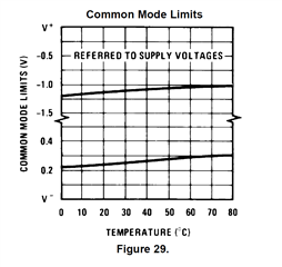
    see the "input voltage range" in the "electrical characteristis" of datasheet and figure 29.

    Kai

  • Hello Kazuya,

    As Kai pointed out, this information is in the "Input Voltage Range" line in the table, and also in Figure 29 "Common Mode Limits".

    It may be confusing because they are assuming split supplies of ±15V. This needs to be "translated" into single supply by finding the difference to the nearest rail.


    To "translate", you find the difference from the nearest supply rail voltage. So for ±15V supplies:

    For MIN, the result is 15 - 14.5 = 0.5V. So the input must be 0.5V above the V- rail.

    For MAX, the result is 15 - 13V = 2V. So the input must be 2V BELOW V+.

    So with these results, you find the single supply voltage limits for a 5V single supply.

    The lower input voltage limit will be the MIN result, or +0.5V (assuming V- = GND, or 0V)

    The upper input voltage limit is 5V - 2V = 3V max.

    This is shown graphically in figure 29:

    Note the V+ and V- on the right scale.

    As can be seen, the upper common mode range decreases at cold...a major reason many customers find things work fine at room temp on the bench, but can fail at cold or hot when hitting the limits.

    The graph shows the operational limits (where failure is expected). The electrical table limits (0.5 and -2V) are much more conservative and guarantee all table specifications (prop delay, bias current, etc) within those limits. We recommend staying within the table limits.

  • Hello Paul, Kai,

    Thank you very much for your reply and I'm sorry to be late my response.
    Your replies are very helpful for the customer and me.

    Thank you again and best regards,
    Kazuya.