This thread has been locked.

If you have a related question, please click the "Ask a related question" button in the top right corner. The newly created question will be automatically linked to this question.

INA229: Measure voltage between -18v to 0v

Part Number: INA229
Other Parts Discussed in Thread: TIDA-00313, INA226

Hi,

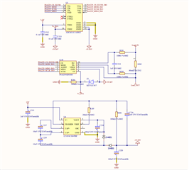
I want to make a circuit that can measure voltage between -18v to 0v using ina229, i have check TIDA-00313 design and make some modifications, blow is my Schematic diagram.

which use a inverter Charge pump to generate negative 19v rail, the ina229 ic get it power form -19v rail and the zener diode.

To communicate with SPI to MCU i use a digital isolator  ADUM1411ARWZ

Please help me to check whether the following circuit can work or not, thank you!

  • Hello,

    Thank you for using the TI forum.  In general the schematic looks fine to me. However, it does not show the voltage at Load_IN and Load_OUT in relation to the INA, so you'll just need to make sure that the voltage there is within the common mode voltage specification in relation to the INA229 GND pin.

    Regards,

    Mitch

  • Hi Mitch

    I have check ina229 spec the common-mode voltage support from –0.3 V to +85 V, but i supply -19 volts at INA229 GND pin, so the common-mode voltage change to –19 V to +66V, it that correct?

    Therefor my load voltage range could be -19V to +66V, is that mean i can measure both positive and negative voltage in this circuit?

    Also how do i connect my VBUS pin, i see some design just connect VBUS pin to gnd is that correct?

    Best Regards, thank you very much for answering my question.

  • The design i saw in the forum

  • Hello, 

    Yes, your understanding is correct that your common mode voltage can go from -19V to +66V (You just need to make sure that the low sides are connected so that the load and the INA's potentials are referenced to each other.). Based on how you connected your VBUS pin in your schematic above, i'm guessing you are measuring high side, in which case your connection is fine as long as the bus stays below +66V.  If you connect the INA on the low side, then you do not have a limit on how high a voltage you can use, but you would have to divide down the VBUS if you want to measure it above +66V, and then adjust the results from the registers accordingly. (Similar to how it is done in TIDA-00313). 

    If they connected VBUS to GND, then they probably just weren't using features that require VBUS (probably because the INA226 can only do 36V, and their VBUS was 56V above the INA's GND, and they did not need the features enough to want to divide the bus voltage down to a usable range).  

    Regards,

    Mitch

  • Thank you that clear all my question