This thread has been locked.

If you have a related question, please click the "Ask a related question" button in the top right corner. The newly created question will be automatically linked to this question.

OPA325: OPA325

Part Number: OPA325
Other Parts Discussed in Thread: OPA1678

Hello,

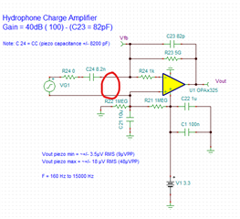
 I built this amplifier and it works well even if it is more sensitive using a 120 pF piezo instead of 8.2 nF or adding a 120pF capacitor in series with the 8.2 nF piezo.

Now I receive customer inquiries to connect this hydrophone with coax cable like RG 323 which needs a power over coax connectivity and change the original design.

Do you know how to select the inductors value on both sides of the circuits for such application?

Thank you,

Kind Regards,

Guy

  • Hi Guy,

    Can you post a schematic?  We won't be able to help with this unless there's a clear way to understand this.

    Best Regards,
    Mike

  • Hi Mike,

    Sure, you will find out the circuit that I would like to modify on this link:

    https://e2e.ti.com/support/amplifiers-group/amplifiers/f/amplifiers-forum/1133669/opa325-opa325

    Kind Regards,

    Guy

  • Hi Guy,

    Ok - you are now saying that the piezo will be connected with a cable between the amplifier and the element (shown as C24), correct?  

    This will certainly add bulk parasitic inductance and capacitance.  Will it have 2 conductors and a separate ground shield?  Do you have an estimate of maximum length?  

    Regards,
    Mike

  • Hi Mike,

    No, I don't want to connect the piezo to the op amp with a coax cable because I know that it doesn't work very well due to the very, very low voltage coming out of the piezo.

    What I need to do is to power the amplifier and carry out the output signal on a 2 wire cable like a coax instead of a 3 wire cable ( ground, power, signal).

    I know that it can be done because these types of hydrophones are available on the market.

    Is Phantom Power could be used?

    Poc is used to carry out digital signal camera over coax, but I didn't seen any application document for audio.

    Thanks,

    Kind Regards,

    Guy

  • Hi Guy,

    the datasheet of OPA1678 discusses such a phantom powered circuit.

    An alternative method is shown below:

    But such a circuit is only suited for HF signals (antenna amplifiers). With LF signals down to 160Hz L1 and L2 would become huge. 1H would give an impedance of 2 x pi x 160Hz x 1H = 1k Ohm.

    Kai

  • Hi Guy,

    Ok, I got it.  Yes the common way to do this is use a JFET to buffer the piezo.  I made a quick example circuit below: 

    In the example, the JFET basically serves as impedance translation (an argument could be made to make it common-drain, but, similar results), now the piezo is decoupled from the low impedance in the cable.  The cable is biased with 3.3 V, but a pull-up resistor between 3.3 V and the Source on the receiving side will help set the gain of the front end to approximately 1.  R3 is used to bias the JFET.  More elaborate schemes can designed, specifically using a current source instead of the resistor will help boost the gain of the front-end and lower the overall noise.  But, this is the simplest approach and can be modified from here.  The amplifier will then be used in a non-inverting gain of 40.08 dB (101 V/V). to hit your desired gain.

    I attached the design in the post so you can edit for some fine-tuning.

    Note, since this is the last day before Thanksgiving, it is unlikely you will hear from anyone until next Monday.

    Best Regards,

    Mike

    JFE150_Front_End.TSC