This thread has been locked.

If you have a related question, please click the "Ask a related question" button in the top right corner. The newly created question will be automatically linked to this question.

LMP8646: LMP8646 design review

Part Number: LMP8646
Other Parts Discussed in Thread: LM5022, , LM5118, TINA-TI

Hello Team,

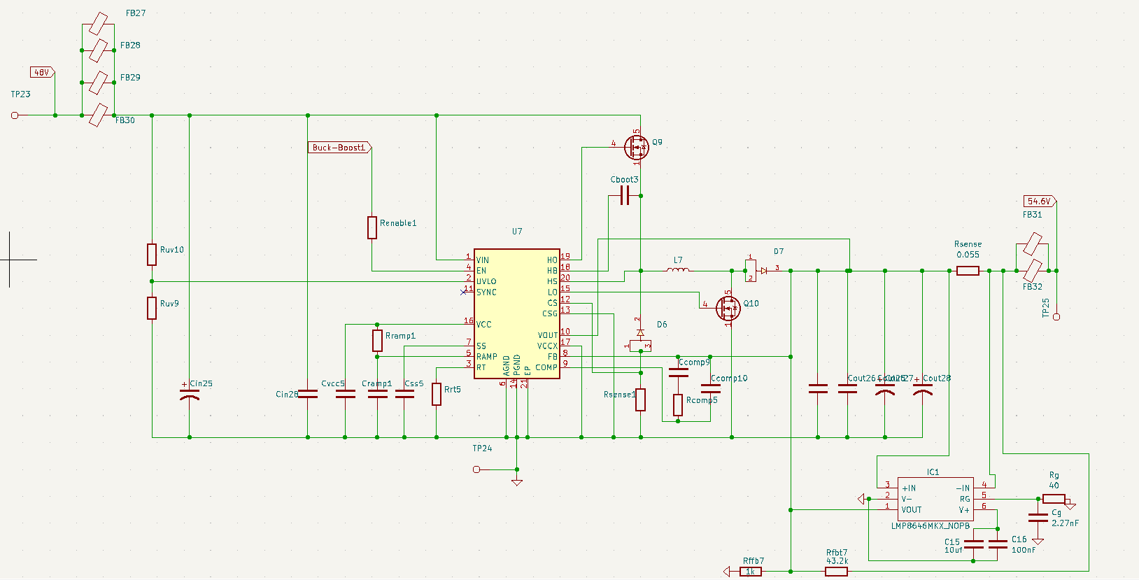
                    We want to use the LMP8646 to use the LM5022 as a CC and CV source.We needed some help in reviewing our design. The design is current limit of 2A. Output voltage from LM5022 is 54.6V. We got the 

output accuracy as 5.55%, Gain resistor 56.8K but approximated to 58K, is this ok?

Output resistor requires the minimum voltage  (VO_REG_MIN),how do we find this for our application,or do we put the default 50 ohm?

We have taken BW recommended in datasheet 1.75K

and sense resistor as 55m ohm

A review on this would help us a lot

Thanks

  • Hello,

    The LM5022 has a current limit function, will this not be used?

    As far as the LMP8646 with a current limit of 2A across a 55m ohm sense resistor you will generate 110mV.

    With 110mV Vshunt output of the LMP8646 is (with your Rg) 1.2496V the FB voltage of the LM5022 is 1.25V so this will work. There will be some error as you mentioned.

    Depending on your load the Rout will be important. If you will only have resistive loads then you can pick Rout = 50ohms. If your load is for example a super cap which does not have the load current proportional to the output voltage you will need to pick an Rout to have tolerable output current error at startup.

    Regards,

    Cas

  • Hello Castrense,

    Our application is charging a battery (capacitive type load) using a Buck-Boost controller(LM5118),  (Not the LM5022 as we found out). we start charging the battery from 42V, so should I consider 42V as the minimum voltage (VO_REG_MIN)?

    Also we could not find the formula to calculate RFBB, RFBT.Is it the values calculated for the LM5118 in the webench design? and since the LM5118 has a current sense pin do we need to use the LMP8646 to achieve CC mode and CV mode.

    Thanks

  • Hello,

    At startup is the LM5118 charging the battery? Or will the battery be switched into the circuit with a stable LM5118 output?

    RFBB and RFBT are the values you will use to create your Vfb for your given output voltage on the LM5118. 

    The last question is one that I cannot answer as I support the current sense products and not switching converter ICs. My best guess is the LM5118 may have a different control structure to control the current limit than regulate the voltage. Using the LMP you will be using the same regulation the converter would use for the voltage.

    Regards,

    Cas

  • Hello Castrense,

    Yes at startup the LM5118 will be charging the battery.So what would you recommend as the as the minimum voltage (VO_REG_MIN)? The battery will be connected to the ouput of LM5118 as soon as the IC is enabled with the help of MCU it will start charging the battery

    Our battery end discharge voltage is 42V.So we would start to charge from 42V to upper charge limit 54.6V

    So should I use the Rfbb and Rfbt values which I obtained from the Webench design of LM5118?

    Thanks

  • Hello Castrense,

    Yes at startup the LM5118 will be charging the battery.So what would you recommend as the as the minimum voltage (VO_REG_MIN)? The battery will be connected to the ouput of LM5118 as soon as the IC is enabled with the help of MCU it will start charging the battery

    Our battery end discharge voltage is 42V.So we would start to charge from 42V to upper charge limit 54.6V

    So should I use the Rfbb and Rfbt values which I obtained from the Webench design of LM5118?

    Also just wanted to confirm that the LMP8646 will make the LM5118 act as CC and CV source.

    Thanks

  • Hello,

    Yes the VO_REG_MIN will be 42V. Yes I am not familiar with the Webench but if that gives you the Vfb resistor divider values for your given Vout then you will use those values.

    The LMP8646 will limit the current. When the current is not being limited the converter will limit the voltage based on the feedback. 

    Be sure to use a Vs of 5V as per the datasheet case 3 on page 14.

    Regards,

    Cas

  • Hello Castrense,

    One final clarification

    Could you please kindly just take a look at this schematic of the LM5118 with the LMP8646 connected to it to verify if it is properly connected. I have some doubts as there are COMP pin connections to the FB pin with the help of resistor and capacitor.

    Also in the LMP8646 datasheet they have used 10nF capacitor to connect FB pin to Lout trace. In the schematic I have shared I have not used any capacitor, should we use a capacitor? Do we go with 10nF capacitor? as there is no formula to calculate the value of this capacitor.

    Or do we not connect FB pin to Lout trace? but I think we need to connect to regulate voltage when not limiting current

    Thanks

  • Hello,

    You should not connect FB to Lout trace. This will prohibit the regulation of the output. You can either not connect the FB to Lout (open) or have a 10nF cap as mentioned in the LMP8646 datasheet. 

    As far as the LMP8646 the Rg is 40 ohm? I believe we specified a different value for this, and there is no Rout in this schematic.

    For the COMP pin I will refer you to the team that handles the LM5118 as they will be able to assist you.

    Regards,

    Cas

  • Hello Castrense,

    There seems to be some value mismatch in the schematic

    Here are the final design values for 3A current limit with the LM5118

    Fbv(LM5118)=1.23V

    Sense resistor is 0.055 ohm ,Sense voltage is  0.165V

    Gain Resistor is 37.3k approximated to 40K

    Bandwidth Capacitor is 2.27nF for BW of 1.75k

    %Error of I=5% so 3.15A

    Rout=536.58 ohm approximated to 540 ohm

    Rfbb and Rfbt are 1k and 43.2k respectively

    Could you just let me know if these values are acceptable 

    Thanks

  • Hello Bhanu,

    Please use the calculator for the values of the LM5118 circuit: https://www.ti.com/lit/zip/snvu065

    The regulation of the LMP8646 need to be a lot slower than the one of LM5118.

    For the final decision about the values, you need to build the circuit and then test it out.

    In general the schematic seems to be ok, I recommend adding gate resistors and snubbers across the switches in case this is needed.

    BTW, please follow good layout rules, see the 4 articles that start here: https://e2e.ti.com/blogs_/b/powerhouse/posts/four-switch-buck-boost-layout-tip-no-1-identifying-the-critical-parts-for-layout 

    Best regards,
    Brigitte

  • Hi Bhanu,

    it's not a simple task to add the LMP8646 to the LM5118 because every change in the feedback loop bears the risk of destabilizing the LM5118 by introducing unwanted phase lag. I strongly recommend to carry out thorough TINA-TI simulations of your circuit before building it up and making exeriments and measurements with it.

    Below you see two transient response simulations with and without the LMP8646 being included in the feedback loop of LM5118:

    bhanu_LM5118_LOAD_TRANS.TSC

    You will notice that some additional fine tuning of the ciruit is necessary to make it run properly and stably.

    Kai