This thread has been locked.

If you have a related question, please click the "Ask a related question" button in the top right corner. The newly created question will be automatically linked to this question.

INA199: Internal resistance between Inputs

Genius 16430 points
Part Number: INA199

Hi Experts,

Good day.

We would like to ask, as per THIS old thread:

How this 2.5Kohm input resistance aligns with "Table 1" in the INA199 datasheet, where input resistance (for gain of 50) is 20kohm?
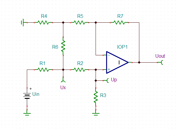
Also is it possible to attach a simplified schematic (like on page #1 in the datasheet), to clarify where the 1.25K resistors are?

Happy Holidays!

Regards,
Archie A.

  • Hi Archie,

    I cannot open your link.

    Equation 1 in section 8.4.1 of datasheet of INA199 becomes correct when you assume a 2k5 resistor between the inputs in the "Bias" box in figure 21. "Rint" is shown in Table 1.

    The "1250" in the formula is gained by calculation and is just half the 2k5 resistance of the "Bias" box. Also keep in mind that the internal circuit shown in figure 21 is highly simplified. Much more is going on internally than shown.

    More, I would be careful with the word "input resistance". "Rint" is the internal resistances at the inputs of INA199 according to figure 21. But this is not the input resistance of INA199. For a pure common mode input voltage, which means an identical input voltage at both inputs without any differential input voltage, each input sees an input resistance of about 1M + Rint. For a pure differential input voltage without any superimposed common mode input voltage, on the other hand, there is a 2k5 resistance between the inputs.

    Unfortunately, when you have a mix of a common mode input voltage plus a differential input voltage across the inputs, the situation becomes highly complex and you can no longer talk about a "common mode input resistance" or a "differential input resistance" or even an "input resistance" of INA199. It's better then to talk in terms of input bias currents and input offset current. In the very most cases (with a meaningfully low shunt resistance) the "input resistance" of INA199 is so high that it can be neglected anyway. This does not apply to the input bias currents of INA199, of course, which originate from the "Bias" box in figure 21, by the way.

    Kai

  • Thanks Kai, for these very informative inputs.

    Happy Holidays!

    73,
    Archie A.

  • Hello all,

    Kai has given a great answer and from the old thread the main takeaway is to especially consider Ib when measuring small currents with big shunt resistors as this will contribute to more error.

    Regards,

    Cas

  • Hi Archie,

    the "Gain Error Factor" shown in equation (1) of datasheet of INA199 can be found this way:

    archie_ina199.docx

    Kai