This thread has been locked.

If you have a related question, please click the "Ask a related question" button in the top right corner. The newly created question will be automatically linked to this question.

OPA690: output voltage

Part Number: OPA690
Other Parts Discussed in Thread: DAC2904, , TINA-TI, THS3217, THS3215

Hi team,

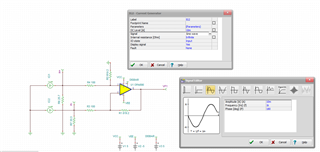
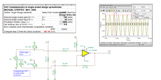
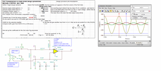
There is a question about DAC2904 output current to voltage conversion circuit. The customer is using OPA690 to implement this conversion.

The circuit is shown as below:


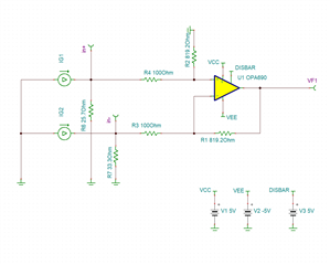
The customer wants the output voltage between -4.096V and 4.096V. But they found the TINA simulation result mismatch with their expectation.

The output is between -4.07 and 3.2V.


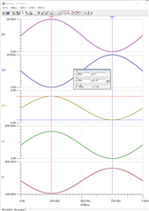
The TINA-TI simulation file is attached. Can you please help to review and give some suggestions?

High_speed_DAC_V2I.TSC

Thank you!

Regards,

Ivy

  • Morning Ivy, 

    This is a deceptively difficult design flow as the summing junction on the inverting node has a the V+ voltage moving in the opposite direction making that series input R look like and active impedance - reducing it. I had originally worked on this in this application note, but I believe there are some errors hiding inside this one - so just look at it for an idea of the issues. I had made some progress on fixing that analysis not too long ago, it will take some time to find that and move it forward. 

    https://www.ti.com/lit/an/sbaa135a/sbaa135a.pdf

    This also came up in this e2e thread, I pursued it for awhile - enough to get an unlocked spreadsheet in there, but that is still the slightly off spreadsheet - and I think it is slightly off on matching the output swings on the DAC exactly, might give the right Vopp. 

    https://e2e.ti.com/support/amplifiers-group/amplifiers/f/amplifiers-forum/1116966/opa836-updated-complementary-to-single-ended-design-flow

    In the meantime, 

    1. This issue comes up so often we did the THS3217 and THS3215 where the D2S stage in that device solves this problem - it might be more part than you need, but just FYI

    2. You might have the input source set up wrong, to emulate a DAC you need its common mode current then the swing around that, looks like you have bipolar input swing here, 

    3. That +/-4.1V swing is beyond  what the OPA690 can do on +/-5V supplies, might want to increase the supplies to +/-6V or reduce your targets. 

    And that depends on load as well, 

  • Ok Ivy, I made some progress on this using that unlocked original spreadsheet. I had to change some things to get a solution, 

    1. I targeted lower gain, 180ohm on each side which should give a +/-3.6V output

    2. I had to target a higher impedance looking in, 40ohms here that will still hold the DAC output swing below its max compliance, 

    Actually works pretty well - the output swing is right on, the inputs voltages have slightly different swings (above ground) as expected - but not much, the key was that red max gain cell, must be greater than the target which is what led me to reduce the target gain trying a number of combinations. 

    And this file which also has the corrected DAC source current model - that is a 1MHz signal above, 

    OPA690 Comlementary DAC interface.TSC

  • And here I went ahead and pushed this to the full +/-4.096V swing assuming an increased supply is ok, had to increase the input impedance to 50ohm but that is still ok I think, 

    OPA690 Comlpementary DAC interface updated.TSC

  • Hi Michael,

    Highly appreciate for your suggestions.

    I will feedback to the customer and try this solution.

    Many thanks, happy new year!

    Regards,

    Ivy