This thread has been locked.

If you have a related question, please click the "Ask a related question" button in the top right corner. The newly created question will be automatically linked to this question.

TLV1805: Amplifiers forum

Part Number: TLV1805
Other Parts Discussed in Thread: LM311, , TL3016, TLV3601, TLV3501, TINA-TI

hi sir

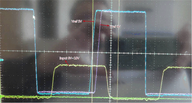
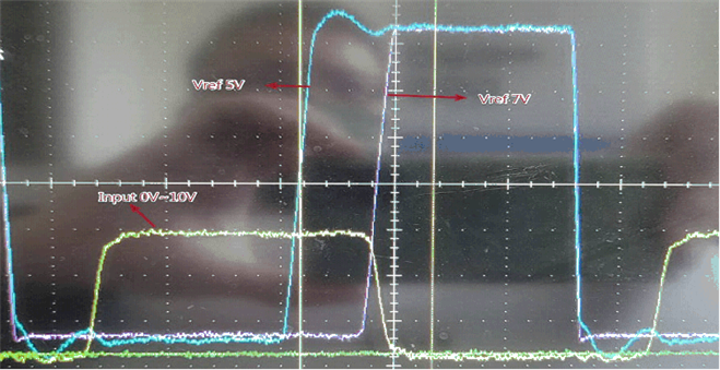
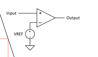
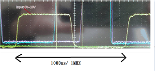
use the TLV1805DBVR to be a comparator, one input is a square wave, another pin input different voltage from 5~9v

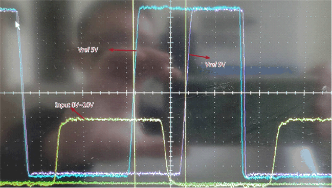
the output wave will have longer propagation time when input voltage rising , as below figure

could you advise it? thanks

i need a comparator which output waveform is less propagation delay, when different voltage from 5~9v


  • Hi Alex,

    plese show a schematic. Also, what is the time scale of your scope plots?

    Kai

  • Like this

    Positive input is a  fix square wave, negative input is Vref which from 5~9v

    200/time scale。yellow Waveform is 1MHZ Square wave


  • Alex

    thanks for your post.  You are seeing the effect of prop delay variation with respect to overdrive (see fig 39 and 40 in datasheet).  In the case of 9V reference, the input signal is probably just barely going beyond the reference and thus the prop delay is longer.  in the opposite direction, high to low, you see the prop delays nearly match because the overdrive levels are quite large.  In the future when sharing oscilloscope screenshots, please do not crop.  We need to see all the information such as volts per division, time, and where the ground references are.  Better picture to share would be both inputs and output waveforms on same screen.  We really don't have much faster devices at over 5V operating voltage.  You could consider LM311 family but it has some drawbacks.  If any additional assistance is required, we will respond on Jan 3 when we return from holiday break.

    Chuck

  • hi Chuck

    TLV1805's propagation delay is over sepc. I need another device for my project.

    The key spec. as follows

    1. Propagation delay less then 20nS
    2. Common-mode input voltage range at least -3.5V ~ +3.5V. Bigger range is better.
    3. Cost and Size need to be consider.

    Please advise me the suitable device.

    Until now, I found TL3016. but I don't understand Propagation delay vs Input impedance

  • Alex

    I wish I had a good answer for you.  I can interpret two ways since this d/s was created in late 90's and we can't confirm.  If it is really tpd vs input impedance, I can only assume that input impedance times input bias current would create offset that needs to be overcome and thus this could shift prop delay but it would depend on slope of the input waveform.  Another interpretation is that they meant to say output load impedance since it is right next to the load cap plot.  So there could be potentially some parasitic filtering of the output and this could impact prop delay.  As you can tell, I am really stretching for any possible explanation.  My honest opinion would be to not worry about that plot and focus on the prop delay vs over drive which is really your most important spec.  Looking at the curve for this in the datasheet, they zoom in quite a bit and don't show how much it improves with much larger levels of OD.  But being a much faster device, I would not expect the large amount of variation that you experienced on tlv1805.

    Chuck

  • did you have any advise parts in TI?

  • Hi Alex, 

    Are you looking to operate split supply to allow for the common mode input voltage to go negative? Keep in the mind the output will now swing negative VEE to VCC. With that speed, we have TLV3601 and TLV3501. 

    If you would like to go split supply on the input but have a ground referenced output, we have the LM319 but it is not fast enough fir your application.

  • Sorry Alex for the confusion

    we don't have anything better to offer than the TL3016.  If you power with +/-5V, you can handle inputs of +/-3.5V and you should obtain less variation in prop delay for your references.  This device also has the advantage of having a separate GND pin, so even if powered with +/-5V, the output will only swing GND to 5V.

    Chuck

  • Hi Alex,

    in the datasheet it is said that the TL3016 is a "functional replacement to the LT1016". So, I would take a look into the datasheet of the original LT1016. And since there is a "propagation delay versus source resistance" curve shown I think your figure 8 may also show the "propagation delay versus source resistance" of TL3016.

    Interestingly, when you open the Spice model of the

    TL3016 TINA-TI Reference Design

    you will find that the Spice model is modelling the propagation delay time versus source impedance:

    So, if I were you I would run a TINA-TI simulation of my circuit.

    Generally speaking, with a so fast comparator the source impedance should be kept way below 1k.for stability purpose. And if you additionally consider the input bias current and input offset voltage of TL3016, then the input resistance should not be higher than about 300R anyway.

    Kai

  • I tend to agree with Kai.  The original intent must have been to include filtering of the input when you consider source impedance and input capacitance.  We just don't usually include this on our newer high speed devices.  But in regards to source impdeance, keeping it as low as possible is also needed for what Kai eludes to.  Input bias current times source impedance can impact input offset voltage on these higher speed bipolar input stages.

    Thanks again for the great support Kai and support of the forum.

    Chuck

  • Alex we have not heard back from you so we will be closing this thread.  Feel free to reply back if you have any more questions