This thread has been locked.

If you have a related question, please click the "Ask a related question" button in the top right corner. The newly created question will be automatically linked to this question.

PGA309EVM-USB: PGA309EVM-USB

Part Number: PGA309EVM-USB
Other Parts Discussed in Thread: PGA309

Luis,

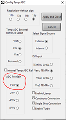
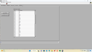
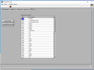
I am having the eeprom problem again. I am hoping this is attached to the thread from a couple of years ago because it explains what was required to remedy the same situation last time. The eeprom has some values populated but not all of them. originally it was because step 7 of the precal file did not have "Continuous Conversion" and "Single Shot Conversion" checked. They are checked now and I am not having any luck getting it to calibrate properly. Note it does get some of the numbers in the eeprom as it gets close to the correct reading. I.E. 4.58v for the 4.5v ideal etc. Again this happened before and was resolved not sure how I lost the recipe as all the Model and Pre-cal files look correct according to your advice.

I have been using the Multi-Cal system for a long time and havent been back to the "PGA309EVM-USB" for a while so I would not be surprised if I am missing something important. We need to have a system for doing one off designs thus the reason I am back using the "PGA309EVM-USB".

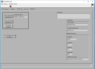
I am ataching the Pre-Cal and Model files for review. I am not using an emmulator file as I am using an external signal source and a PGA309 pcb of our own design that functions well on the multi-cal system.

Best Regards,

Joe

BSTS_Rev.1.txt
[Filenames]
Pre-Cal Filename=BSTS_23.888_-1.111_54.44_poly2_2.12992_3wire_Lidac.txt
Sensor Emulator Filename=""
[Misc]
Comments=""
Serial No=10
Model No=0
Model ID=BSTS Rev.1
Use Sensor Emulator=FALSE
BSTS_54.444_23.888_-1.111_poly2_2.12992_3wire_Lidac.txt
[PGA309_Settings]
Numb Reg=3
Poly Order=2
Output Mode=1
Vout_High_Target=4.500000
Iout_High_Target=0.000000
Iout_Low_Target=0.000000
Vout_Low_Target=0.500000
Vs=5.000000
Vref=4.096000
Calibrate Nonlin=TRUE
Reg0=0
Reg1=0
Reg2=0
Reg3=3328
Reg4=0
Reg5=0
Reg6=5211
Reg7=0
Reg8=0
Temp0=54.444000
Temp1=23.888000
Temp2=-1.111000

  • Hi Joseph,

    I see you are referring to this post: https://e2e.ti.com/support/amplifiers-group/amplifiers/f/amplifiers-forum/981746/pga309evm-usb-after-calibration-is-complete-eeprom-calibration-data-are-all-zeros in which Luis supported you.

    In the old post you were using the 4-wire output mode but it appears that you have switched to three-wire. Can you confirm that you are now using the three-wire configuration on your custom PGA309 board? I will use your Pre-Cal file and attempt to replicate the issue on the PGA309EVM in the three-wire output mode.

    Regards,

    Zach

  • Zach,

    Thanks for the response! Yes I have been using 3wire mode successfully on both the Multi-Cal system and the PGA309EVM-USB. Currently I am directly connected to the USB-DAQ Platform with my custom PCB.

    Is Luis still around or has he moved on? He was a nice guy. Send him my regards and again thanks for looking into this.

    Best Regards,

    Joe

  • Hi Joseph,

    Nice to hear from you; glad you have been successful with the PGA309 application.  Thank you for your continued interest on the PGA309. Zach and I are part of the same team.  Zach will be working to reproduce the issue on the bench, and get back to you as soon as possible.

     Thank you very much,

    Kind Regards,

    Luis

  • Hi Joe,

    Thank you for your patience while I've been looking into this. I was able to replicate the error with incomplete EEPROM values using your pre-cal settings and the PGA309EVM-USB.

    I believe the issue is related to the "ADC Pre Gain" setting in the "Config Temp" section of the pre-cal file. From my tests, setting the ADC Pre Gain to 1V/V allows the EEPROM values to be filled correctly. Try making this change in your pre-cal file, or for convenience I attached the pre-cal file I used for my test. The only difference between these files is register 6 which contains the ADC Pre Gain setting.

    Please let me know if this fix works in your system.

    PreGain1V.txt
    [PGA309_Settings]
    Numb Reg=3
    Poly Order=2
    Output Mode=1
    Vout_High_Target=4.500000
    Iout_High_Target=0.000000
    Iout_Low_Target=0.000000
    Vout_Low_Target=0.500000
    Vs=5.000000
    Vref=4.096000
    Calibrate Nonlin=TRUE
    Reg0=0
    Reg1=0
    Reg2=0
    Reg3=3328
    Reg4=0
    Reg5=0
    Reg6=5203
    Reg7=0
    Reg8=0
    Temp0=54.444000
    Temp1=23.888000
    Temp2=-1.111000
    

    Thanks,

    Zach

  • Zach,
    I tried updating my Pre-Cal but got the same result. I verified that I am using "1V/V". Also I made a Test Model file and used your "PreGain1V.txt" Pre-Cal file it also did not work.
    the calibration went as before. Here is a screen print showing the EEPROM data after calibration. Again the ZM1-16 and GM1-16 data are zero's.
    Please help!
    Best,
    Joe 
    Joe Letkomiller
  • I tried unsuccesfully to upload the image, sorry. note also that I have moved to Windows 11. Do you think this could be the problem?

  • Hi Joseph,

    Can you provide a photo of your test set-up including the connections to the USB-DAQ? A wiring diagram would be helpful as well.

    Do you have a PGA309EVM on hand? Can you connect the PGA309EVM in 3-wire mode to the USB-DAQ and attempt calibration using the sensor emulator? I notice the "auto-continue" feature on the "auto-cal" tab can cause timing issues in the 3-wire configuration so you will need to click the "continue" button manually after each step just as you would with an external sensor.

    The PGA309 software is compatible with windows 11 and I was able to successfully calibrate on both windows 10 and 11 using the pre-cal file I sent previously. Can you provide a screenshot of your "set up cal" tab like the one below? Can you also send your updated pre-cal file that you have been using?

    One more thing for now... go to the "EEPROM" page and select the "load EEPROM with file" button then select the EEPROM file I've attached here. Then use the "read EEPROM" button to verify that the EEPROM is being written and read from correctly. After loading and reading this file your EEPROM tab should look like the image below. Then you compare to the results after attempting your calibration.

    3wire_MN_1_SN_1_DC_423.txt
    [General Info]
    Date=1/27/2023
    Time="2:25 PM"
    [Paths]
    Model path="/c/program files (x86)/proj_pga309evm-usb/Model_Files/JAN27_custTest1.txt"
    Pre-Cal path="/c/program files (x86)/proj_pga309evm-usb/Pre_Cal_Files/PreGain1V.txt"
    Sensor Emulator path="/c/program files (x86)/proj_pga309evm-usb/Sensor_Emulator_Files/nonlin.csv"
    [EEPROM Data]
    Addr0=21577
    Addr2=0
    Addr4=0
    Addr6=3344
    Addr8=10005
    Addr10=0
    Addr12=5203
    Addr14=25406
    Addr16=21472
    Addr18=36153
    Addr20=24940
    Addr22=21582
    Addr24=65388
    Addr26=266
    Addr28=21688
    Addr30=65404
    Addr32=228
    Addr34=21792
    Addr36=65421
    Addr38=183
    Addr40=21892
    Addr42=65442
    Addr44=141
    Addr46=21989
    Addr48=65463
    Addr50=93
    Addr52=22083
    Addr54=65485
    Addr56=41
    Addr58=22174
    Addr60=65506
    Addr62=65522
    Addr64=22262
    Addr66=65534
    Addr68=65464
    Addr70=22346
    Addr72=22
    Addr74=65399
    Addr76=22428
    Addr78=50
    Addr80=65334
    Addr82=22506
    Addr84=86
    Addr86=65258
    Addr88=22581
    Addr90=117
    Addr92=65182
    Addr94=22653
    Addr96=153
    Addr98=65099
    Addr100=22721
    Addr102=196
    Addr104=65002
    Addr106=22787
    Addr108=237
    Addr110=64908
    Addr112=22849
    Addr114=290
    Addr116=64797
    Addr118=32767
    Addr120=0
    Addr122=54559
    

    Thanks,

    Zach

  • Zach,

    Sorry it has taken me so long to respond. I do very much appreciate your support! 

    I followed through with installing the PGA309 EVM in 3 wire mode. It worked properly and calibrated. I realized right away when I hooked it up that I did not wire my device correctly. In this application we are taking advantage of the temperature coeficient of the attached bridge using a fixed resistor on the high side to get the temperature. I am using the Burr Brown sensor emmulator. I made the following mistakes.

    1) I did not connect the temperature wire.

    2) I did not properly modify the circuit board to use the signal from the Burr Brown sensor emmulator. (The sensor emmulator DOES NOT act the same as a resistive bridge! All the signals are buffered with opamps. When connecting my board I must remove the series pass resistor that is used for temperature measurement from the exc pin or the PGA does not calibrate right.)

    I also found another problem. I have 2 USB DAQ Platforms. One is working perfectly calibrating from .5 to 4.5v very well. Unfortunately I was using the one that does not work correctly. It does calibrate but the AtoD converter is not quite right it thinks that 4.585v is 4.5 v and .51 is .5. The computer shows 4.5 v and .5 v respectively on the screen when it calibrates but using 2 different independant meters the output is actually 4.585 and .51v. 

    All these issues made a perfect storm of problems. It is now resolved at least with the correctly working USB DAQ Platform. 

    I have looked at the datasheet for the Ato D converter used on the USB DAQ Platform and may try to replace it to resolve the problem. I have confirmed that the reference used in circuit is working correctly and there really isn much else to test. If you have any suggestions let me know.

    Thanks again for the support!

    Best,

    Joe

  • Hi Joe,

    That is great! Thanks for letting us know how you were able to resolve this issue, it is very helpful when we look back at these threads in the future.

    Just to clarify, you have one working USB-DAQ that you are able to successfully calibrate and write to EEPROM on your device?

    Regards,

    Zach

  • Zach,

    Both USB- DAQ's calibrate the PGA309 fine. It is just that one of them has an AtoD error. THe AtoD reports 4.5v when the actual voltage at the PGA309 output is 4.585v and .5v when it is actually .51v. The computer is displaying 4.5 and .5 respectively during the calibration at every calibration point. The computer can only use the information the AtoD gives it to calibrate and that is what it is doing.

    Just as an experiment I reduced the set points for calibration by .085v and .01 and got a nice calibration of the PGA309 to output 4.5 and .5. The computer thinks it is calibrating to 4.415v (4.5-.085v) and .49v (.5-.01) and displays the calibration points as such but again the actual output is 4.5 and .5.

    I was considering just replacing the AtoD it is only a 6 pin sot-23 packaged part. Note that I verified the reference voltage for the AtoD is correct and the AtoD is internaly self calibrating with no other mechanism to adjust it.

    Best,

    Joe

  • Joe,

    Excellent! Nice catch on the ADC error and I'm glad you found a workaround to keep both your EVMs operating. I'll go ahead and close this thread, please let me know if you need any more support on this.

    Thanks,

    Zach