Other Parts Discussed in Thread: ISO7321FC
Hi Team,
According to our customer, he built this system according to the datasheet and following the steps in Collin Wells' technical blog in the link below.
However, he has some issues as follows;
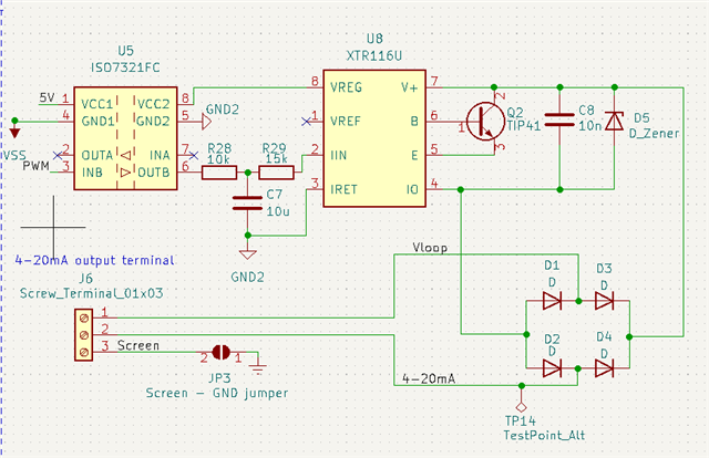
1. The first one is that on VReg he only gets 4.7V.
2. The second is that he can't get less than 7.7mA on the output when he put 0V on the output of the ISO7320.
Please see the schematic diagram for reference. Any idea what causes these error?
Regards,
Danilo