This thread has been locked.

If you have a related question, please click the "Ask a related question" button in the top right corner. The newly created question will be automatically linked to this question.

OPA4141: OPA4141

Part Number: OPA4141
Other Parts Discussed in Thread: TINA-TI, OPA4992

Dear Sir:

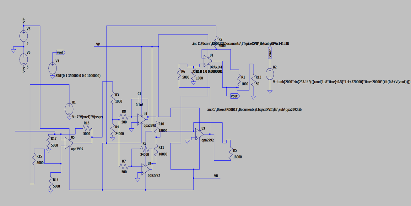
I am using opa 4141 opamp in a PLL to lock a vco system to 350000Hz reference oscillator signal. The error should not be > 0.0003 Hz roughly..

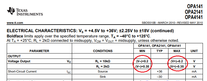
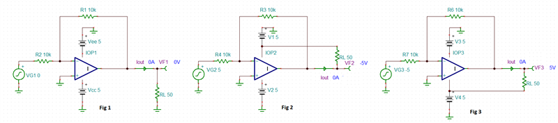
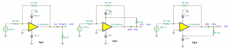
When the opamp that derives the vco with error signal operates near zero output current from opamp, the loop can not lock, but when the operating point of the opamp implies significant current out put the loop locks..The load resistance of the opamp is 50 ohms...

I suspect that the push pull output stage of the opamp in introducing some nonlinearity when the output current is near zero..Is it correct?

Also, do you have any other quad opamp package that has an A type amplifier output stage that can perform well with +/- 5 volts supply..?(instead of AB type amplifier output stage

Thanks

  • No linear class AB op amp output can swing all the way to its rails even if it's called a rail-to-rail output. In case of OPA4141, the output can swing within 200mV of the rail with 10k load and within 350mV for 2k load connected to mid-supply - see below.  Since the output swing is a function of the output current, you need to specify how 50 ohm load is connected in order to determine what output current is sourced or sunk from the output stage.  You also must make sure the output current demand does not approach a short-circuit current of +36mA/-30mA (see below).  Btw, we do not have class A op amps in our precision op amp product line.

    Having said that, you seem to say that you use +/-5V supplies with 50ohm load and zero output current when the loop cannot lock but you do not say where the other side of the load resistor is connected.  In other words, is the output voltage at 0V with 50ohm load grounded (Iout~0) or Vout and load are connected to the same rail (iout~0)?  See below:

    If you use actual OPA4141 instead of ideal op amps shown above, Iout will not be zero in Fig 5 and Fig 6 due to the fact that output cannot swing all the way to rails - see below.

    If you need further assistance, please clarify conditions of your application.  Below I have attached Tina-TI schematic for your convenience. 

    You may download the simulator for free by clicking on the following link: https://www.ti.com/tool/TINA-TI

    OPA4141 Hossam application.TSC

  • I will go through it and reply

    Thank you

  • ok, actually load is connected as in fig 4. Now, if I adjust the opamp operating point to be around zero output, that is, current through 50 ohms could be positive or negative, the PLL does not lock, however if I shift the output voltage to be only in the positive regime, that is, it does not go to negative, the pll locks. in this case the operating point is about +0.4 to +0.7 Volts. The VCO of the PLL loop just adds this voltage to a set voltage by using an opamp adder. Does the simulation model contain some nonlinear model of an AB amplification stage?

    Thank you

  • Hi Hossam,

    the OPA4141 is not designed to drive a 50R load. 50R is way too low and looks like a short circuit. An assumed maximum linear output current of 20mA would allow an output voltage of only 1V across a 50R load.

    Can you show a schematic?

    Kai

  • Hossam,

    The OPA4141 macro-model uses a behavioral architecture and thus no single transistor - for this reason, it will NOT simulate non-linearity of the output stage. Nevertheless, I can think of few possible reasons for the problem you see like cross-over distortion of the output stage caused by sudden high output current switching between sinking and sourcing due to heavy 50 ohm load.  However, hearing about a PLL loop adding between 0.4V to 0.7V to the output by using an op amp adder, I would be also concern about running into a short-circuit issue Kai alluded to.  This is especially more likely if you operate the circuit at cold temperature - see Isc vs temp graph below.  Keep in mind that the graph below is a typical and may further vary over wafer fab process variation.

    All in all, to say anything more about any other possible cause of the issue, we would really need to see the full schematic of your application instead of you describing the circuit - a picture is worth a thousand words.

  • I am trying to upload the circuit...Doc11.doc

    can anyone advice me about how to past the image of the circuit? should I use some specific format?

    I agree the temperature is below zero...I am going to try another opamp with higher short circuit current...

    Also the input voltage to the vco system is between 0 to 2 volt after adding the signals, for this i used the opamp to attenuate from +/-5 to 0 to 2 volt or fro +/-5 to +/- 1 volt which did not work. I could use a 200 ohms resistance with the 50 ohms to force the voltagr on the 50 load to be +/-1 volt too...

    However I will use opa4992 opamp instead, or may be 2 of them in parallel...

  • Hi Hossam,

    to post a picture use the "Insert" button at the bottom of text input window and click "image/video/file".

    I'll post the schematic for you:

    Kai

  • I used opa4992 opamp, and it performs better..

    Now, I am going to use 2 opa4992 in parallel to see the outcome...

    I appreciate it if you can send me a link to info about best ways to use this opamp in parallel...

    Have a good day

  • OPA4992 is a general purpose part with higher short-circuit current than OPA4141 but its IQ is 2.4mA per channel.  A better choice may be TLV4197 with IQ of 1mA and short-circuit current increasing above 70mA at low temp so you don't have to parallel two op amps to boost the output current - see below.

    If you still want to try paralleling two op amps to boost the output current, there are several different ways to do it.  In general, you must include a small balancing resistors in series with the outputs to eliminate the effects of different offset voltage of each op amp - otherwise, one op amp would get into a short-circuit condition while the other would provide a minimal output current drive - see a blog below discussing the topic:

    https://e2e.ti.com/blogs_/archives/b/thesignal/posts/paralleling-op-amps-is-it-possible