This thread has been locked.

If you have a related question, please click the "Ask a related question" button in the top right corner. The newly created question will be automatically linked to this question.

INA190: Current Sense Amplifiers vs Instrumentation Amplifiers for Current Sense accuracy with Differential ADC

Part Number: INA190
Other Parts Discussed in Thread: INA851, INA333, INA290, LM7705

Hello TI E2E,

I have a programmable current source that can range from less than 1mA to over 6A. It has a low side power resistor (~0.45ohms), and the voltage across this with a kelvin connection will be used to measure the current with a fully differential 3 channel 24 bit ADC. These ADC channels can also be turned into 6 single ended channels as well. The accuracy of this voltage measurement will be critical to the error in the programmable current. Brainstorming a way to obtain an error as low as possible is the reason for this post.


I have read many sections of TI's website on programmable gain amplifiers, current sense amplifiers, and instrumentation amplifiers over the past two weeks and am trying to finalize this design. I am strongly leaning towards using either 3 current sense amplifiers or 3 instrumentation amplifiers to measure the voltage with a specific gain dependent upon current level (or some combination of the two). This measured voltage will be used to calculate the current and then a control algorithm will be used to control current variations. For instance, if one of the amplifiers had a gain range of 200V per volt then this could be used to sense currents from 100uA to 30mA. Another amplifier with a gain of 25 could be used to sense current ranges from ~ 30mA to 300mA. Finally, an amplifier with a gain of ~ 1V/V could be used to sense currents from 300mA to 6A.

Specifically, I was thinking of using the INA190 family of current sense op amps to sense the very low current ranges (gains of 200 and 25) and an INA851 with a gain of 1 for the high current range.

The INA851 is fully differential output while the INA190 are single ended. I am cautious of very small ground differences between my ADC and these INA190s to be slightly different and multiplied with the gain could add significant error. Therefore, I believe that using 3 INA851 or another fully differential input and fully differential output op amp with these 3 gains might be a better option because the ADC is also fully differential.

Can you please provide me with some guidance on this issue? Would you recommend using three INA851 because of the fully diff input and fully diff output. It also has very high accuracy and options to have multiple gain values if dependent upon external resistor Rg.

Thank You For Your Help,

Brendan

  • Hello,

    It seems that you will not be able to use the current sense amplifier at the high current with the Rshunt chosen. It will cause the output of the INA190 to saturate. You could try sizing the Rshunt to get most usability between the 3 current domains. With proper layout there should not be potential differences between the INA GND and ADC GND.

    Also keep in mind the Rshunt will need to dissipate 16.2W at 6A with a 450m ohm shunt. 

    The issue with using instrumentational amplifiers is having the correct operating voltages at all nodes of the amplifier. Since you are measuring with 0V common mode the instrumentational amplifiers need a negative supply. The advantage of these is the gain flexibility as you mentioned.

    Depending on the power supply rails you have at your disposal you could use the INA851, keeping in mind you cannot violate the voltages at each node of the amp. If you are able to have a +- supply that is more than 2.5V you can use the INA851 differentially to the ADC. I would follow the suggested circuit to drive an ADC with the INA851.

    You could also use the INA190 for the low currents and the INA851 or INA333 for the higher currents. The INA190 will have better gain error than the INA851/INA333. As the gain error will depend on the gain resistor you place for the INA851/INA333. 

    If you are planning to use the INA190 I suggest using the INA290 it is a more accurate device but has lower bandwidth. Also place an input filter with resistor of 10 ohms and a differential input cap on each INA190/290.

    Regards,

    Cas

  • Hi Cas, 

    Yes, The shunt is really 2 large power resistors mounted to a large heatsink with constant airflow. 

    Regarding the power supplies, I have a 12V, ground, and a -7.5V. I have 3.3V voltage regulators for digital and analog side. I can add linear regulators if needed. 

    Thanks for the suggestion of the INA290. I also had the idea that using the REF pin of the INA 190 to be 100mV above ground and then buffering that signal to the low side input of my differential ADC would essentially make it a differential measurement. Any thoughts on that? But I do agree that potential ground differences could be negligible with proper layout. The INA290 does not have this ref pin.

    With regards to sizing the power resistor, I could have a relay that switches between a higher resistance power resistor at lower currents but want to test the board without this at first. Thanks for the suggestion of the INA333 I liked the INA851 because it has the ability to clamp. I also think if I use gain of 1 then RG and G02+- are not connected which gets rid of some gain error. 

    Thanks a lot for your help,

    Brendan 

  • Hello,

    Since you can use the INA190 in whatever gain for the first two ranges, we can choose the correct one to have swing low and swing high not be a problem. If you go with current sense amplifiers the best option would be a single ended to the ADC. The only issue is measuring the high current.

    So for the high current you can use an instrumentational amplifier. This comes with not violating common mode with the correct power supplies. I suggest the INA333 circuit in a configuration that Zach Olson previously mentioned to you.

    Your idea about using the ref pin as a differential minus will work. But adding that reference voltage will limit your current measuring range. So the cases below you can do with a reference voltage and the output will be Rshunt*I*G between Vout and ref pin. But once again adding the reference will cost you current range and a reference or you will have to use a voltage divider and buffer it to the ref pin.

    Here is some math to make my claims:

    100uA to 30mA: INA190 200V/V power supply 3.3V and GND. Ref = GND. Output = Rshunt*I*G+Vref. 

    Output = 9mV to 2.7V. Output swing of the INA190 is max from gnd = gnd + 1mV. So the 9mV output is fine.

    30mA to 288mA: INA190  25V/V power supply 3.3V and GND. Ref = GND.

    Output = 337.5mV to 3.24V. Output swing of the INA190 is max from Vs = Vs - 40mV = 3.3- .04 = 3.26. So the 3.24V output is fine.

    288mA to 6A: INA333 1V/V power supply 3.3V and -232mV. Ref = GND.

    Input of INA333 V- +.1V, so we must have V- <  -0.1V. There is a reference made for this exact purpose: LM7705.

    Output = 129.6mV to 2.7V. Output swing of the INA333 is max from V- = V- + 50mV. So 129.6mV is fine. output swing max from V+ = V+ -50mV. So the 2.7V is fine.

    When the current goes higher than the range for the corresponding amp the Vswing high will be the highest voltage the output can be. If you are powering the ADC from 3.3V this will protect the inputs of the ADC.

    Regards,

    Cas

  • Thank you. I am going to need to find an op amp that is in stock though. Is TI inventory accurate of having 0? octopart also has 0 from North American suppliers. 

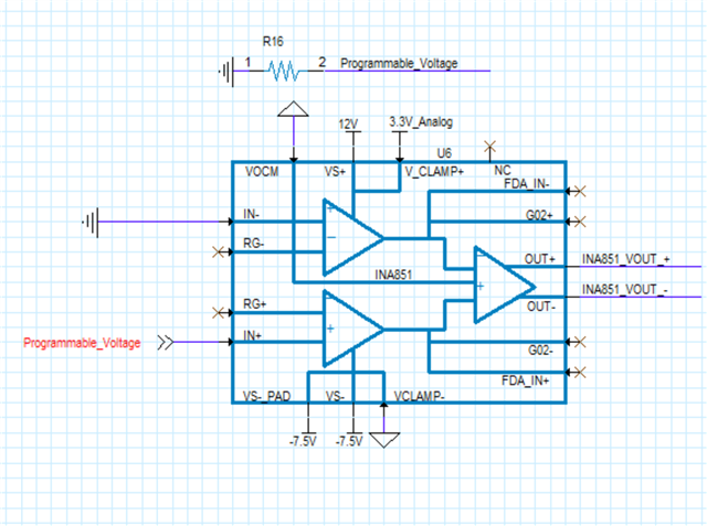
  • Was very convinced to use the INA333 op amp but it has no availability and INA 851 does. Would this be the appropriate wiring for INA 851 in this situation? Current resistor is shown. Without simulating I believe these to be:

    RG and G02 are NC so Gain is 1. no gain error contribution due to resistor. 

    The VOCM is set to ground which should limit the outputs to have INA851_VOUT- to be at ground and INA851_VOUT_+ to be at programmable_voltage's voltage. Assuming that current is only one way towards ground. Alternatively, VOCM slightly above ground would have positive DC offset to output signal. Is this correct? This input does not need to be buffered. 

    Clamping should limit outputs to slightly beyond clamping voltage with very limited current. 

    FDA_IN do not need connections. 

    Non symmetrical supplies are ok. 

    Will simulate with TINA when possible. Feedback on implementation would be greatly appreciated. Differential outputs will go directly into adc with small filter. I also see there is a great excel sheet. 

    Would loved to have used INA333 and if TI has stock I will but, in the meantime I have to work in real world with parts that are available. 

    Best,

    Brendan

  • Hello,

    Yes I can understand your frustration with the stocking issue. 

    I am currently looking into this (FDA schematic) allow me some time and I will get back to you with an answer.

    Regards,

    Cas

  • Hello,

    Your intuition about the circuit is correct but there is one problem. The Vocm pin must be 1V above the Vclamp- pin.

    Besides that the circuit looks fine you will need to make sure that the GND on IN- is kelvin connected to the resistor.

    You could use a precision op amp with the  LM7705. Place it in a difference topology with a gain of 1V/V.

    Regards,

    Cas

  • Hello again,

    If you are keen on using an FDA I would post your circuit requirements (to the FDA team) and have the FDA experts help you select one. My knowledge on all of TIs FDAs is limited. 

    Regards,

    Cas

  • Hi Cas, 

    I will just change the Vclamp configuration and use that. Thank you for all the support. 

    Best,

    Brendan