- Ask a related questionWhat is a related question?A related question is a question created from another question. When the related question is created, it will be automatically linked to the original question.
This thread has been locked.
If you have a related question, please click the "Ask a related question" button in the top right corner. The newly created question will be automatically linked to this question.
I'm looking for a suggestion to interface to a sensor that provides a floating differential sinusoidal output of 300mV pk-pk. We would like to translate that into a digital square wave of 3.3V or 5V. The sensor is a flowmeter that adjusts the frequency based on the flow rate. I believe we would want to use an instrumentation amp with a gain of 10x and connect a resistor between the inverting input side of the amp and our ground to provide some reference. But I'm not really sure as this isn't my area of expertise. Any suggestions would be very much appreciated!
Thanks
Hi Bill,
What is the differential sinusoidal 300mVpp frequency? I can provide the simulation for you if I have the rest of the design information. What are available power rails in your design? Please confirm the following design concept.
300mVpp differential sinusoidal input --> Instrumentation amplifier with gains = 10 V/V --> 3Vpp sinusoidal, single ended output? --> Generate sinusoidal PWM with 3.3V or 5V square wave (what is the proposed modulated PWM frequency in the design).
Best,
Raymond
Hi Bill,
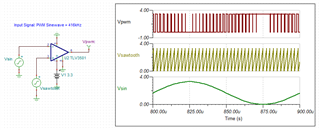
Here is how to generate sinusoidal PWM output, if you want a simple reply. You need to use comparator to generate the modulated signal at high frequency. Please keep in mind that the switching harmonics may affect your analog signals, and this is why you need to increase the PWM modulated frequency above certain frequency in a system.

If you have additional questions, please let me know.
Best,
Raymond
Hi Bill,
I am going to close this inquiry. If you have additional questions, please let us know.
Best,
Raymond
Hi Raymond, thank you for the response. I don't really have a ability to generate a sawtooth. My plan was similar to what you're proposing. I was going to use an Instrumentation amp and pass that through a schmit input logic device to square up the output.
My main concern and point of confusion is how to properly reference the floating source to the amp. My understanding is that providing a 10k to 100k resistor between the (-) terminal and board ground is needed to provide some connection between the floating source and the interface board. I noticed in your comparator simulation you just connected the (-) side of the floating source directly to your system ground. Perhaps I'm overcomplicating this and I simply need to do the same, short one side of the floating source to my board ground. Is that correct?
Thanks!
Hi Bill,
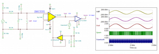
Here is a floating signal to sinusoidal PWM conversion example. Since I do not know how the differential input is configured, I assumed that the setup is configured with dual supply rails. Single supply voltage rail will work as well, but you will need to watch out the common mode voltage at the input.

INA826 Floating input 02152023.TSC
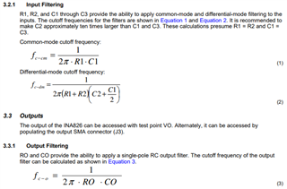
I placed differential and common mode LPF at the AFE, your application may or may not need it. If it is required, please see the attached application note about its configuration.

I selected INA826 because the part is low cost, high performance instrumentation amplifier. We have plenty other one that may perform better than INA826.
If you have additional questions, please let me know.
Best,
Raymond
Hi Bill,
Perhaps I'm overcomplicating this and I simply need to do the same, short one side of the floating source to my board ground. Is that correct?
Yes, this is one option. In this case you even would not need to use an instrumentation amplfier. A simple OPAmp would do.
The key question is: Do you need the isolation at all? If not, then go with your grounding idea and take a simple OPAmp. But if isolation is still necessary, you may provide the isolation later in the signal path as well. Then, take a simple OPAmp, connect the sensor with one end to signal ground of this OPAmp circuit and keep this whole circuit, including the supply voltage of OPAmp circuit isolated from whatever you want to have isolation from. The isolation barrier can be traversed later by the help of an optocoupler (after digitization of signal) or similar.
Kai
Hi Bill,
I am going to close this inquiry. If you have additional questions, you may still open the thread.
Best,
Raymond