This thread has been locked.

If you have a related question, please click the "Ask a related question" button in the top right corner. The newly created question will be automatically linked to this question.

INA220: Low Current monitoring of MCU and Peripherals

Part Number: INA220
Other Parts Discussed in Thread: INA238

Hi Experts,

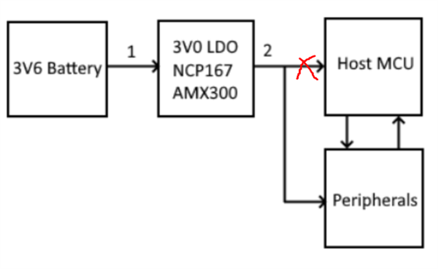
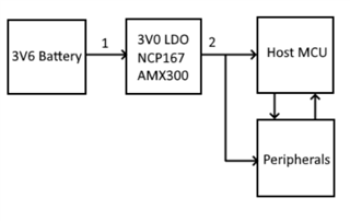
Our customer has an IoT device whose system is briefly outlined in the image attached. When in low power mode, said microcontroller draws around 22uA. To ensure this mode they would like to monitor the current at either Position 1 or Position 2 (he doesn't think that before or after the LDO should make a big difference since it's linear). What solutions would you have in this case, please? Said solution needs to communicate the current draw with their Host MCU through an ADC/Digital Interface such as I2C etc.

I am not sure if this is the right forum for this concern but I would appreciate your advice and/or if you could move this to the forum that best handles this concern if needed. Thank you. 

Best regards,
Gerald

  • Hello,

    In position 1 or 2 you will also measure the peripherals current draw if they are on or their leakage if they are off. Can this be a problem?

    What is the max current draw expected of the system as you are placing it in position 1 or 2 so it is total current draw of the system. This is important to choose an appropriate device.

    So if you want to use the INA220 here are some basic calculations:

    Using PGA = 2 Max Vshunt = 80mV

    To measure 22uA with 1% accuracy we can use Rshunt = 568 ohm. Vshunt (22uA and Rshunt = 568 ohm) = 12.496mV, Max current can be measured is 140.84uA as the max Vshunt (with PGA = 2) = 80mV.

    You could switch PGA if the max current expected is higher. Also could use a lower Vos part to bring the Rshunt down and extend the current measurement range. For example the INA238 is much better with 5uV offset allowing you to make 1% error measurement at 500uV shunt voltage. Decreasing your Rshunt increasing current range.

    Regards,

    Cas

  • Hi Cas,

    Our customer has additional concerns as follow:

    1. We generally measure the current from position 1 thus this is fine. Our average current is 22uA with maximum peaks of 500mA-1A.

    2. Having said this we would like to ensure that the system is at 22uA at certain times and not specifically measure the maximum current or so.

    3. Should we use high-side or low-side sensing?

    Our current profile in sleep mode with an average current of 22uA has periodic short peaks of 15mA every 2.5 seconds. Thus to measure an average current of 22uA, would said peaks of 15mA interfere with the measurements?

    Thanks and regards,
    Gerald

  • Hello,

    1, The problem here is if 1A flows across the resistor we must ensure it can handle the power. That is why I asked about this.

    2, Yes the calculations were for 22uA. But now the design must change as we need to be able to dissipate the power at the higher current. Therefore we need to choose a smaller resistor, since we need a significantly smaller resistor we cannot achieve the accuracy at such low current. We will need to calibrate the system or choose a better INA for the job.

    3, This does not matter that much since you are working with low voltage common mode.

    4, This can be ignored in code. Or you could average and sample for a longer time.

    What error can your customer tolerate on the 22uA measurement? 

    Regards,

    Cas

  • Hi Cas,

    Please see below for customer feedback:

    1. Does the INA220 have an enable/disable switch? We can enable this measurement only when needed/expected to be low power. Furthermore the 15mA BLE current spikes can be switched off in code to further ensure 22uA only.

    2. Check (1) - if we enable the INA220 only when we expect low power there should not be this issue per se. Is the resistor part of the INA220 or do we need to include it as part of our circuitry? We'd like a way to switch it out of the circuit too.

    3. Anything between 20uA to 30uA is fine with us since currently low power mode ranges from 22uA to 25uA. Thus that would mean an error of +-30% (correct me if I'm wrong).

    Thank you and best regards,
    Gerald

  • Hello,

    1, There is a shutdown of the INA using the configuration register.

    2, The resistor is additional circuitry. You can switch it it out of the circuit but this will introduce error (depending on how you do this). If you do not switch it out there is still the problem of the resistor being able to dissipate that power. Putting the INA220 in power down mode will not solve the power dissipation problem of the shunt. 

    3, Okay so accuracy is not a big issue then we can choose a smaller shunt. 

    I would like to ask if you are only interested in the uP low power mode why not place the current shunt here:

    I do not think that 500mA-1A will flow here so our restriction will be less on the power limit of the resistor.

    Regards,

    Cas