Other Parts Discussed in Thread: LM2903B
Hi Expert,
I'm calculateing the value of the hysteresis input with LM2903B.
However I found the difference between similation results and caliculation results.
Could you please let me know the reason of those difference?
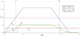
<Similation results :Tina_TI>
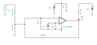
Rhys=500kohm
Rtop=100kohm
Rbottom=47kohm
Vref=3V
Vpullup=5V
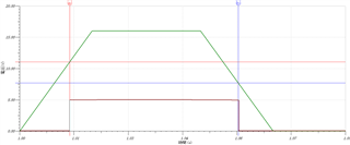
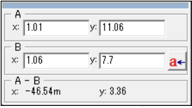
Vr= 11.06V
Vf= 7.7V
<Caliculation results>
Is my following caliculation correct?
Vr = Vref x (Rtop + Rbottom // Rhys) / (Rbottom // Rhys) = 9.983V
Vf = Vref + (R1/R2)xVref - (R1/R3)x(Vcc-Vref) = 8.983V
Could you please give me your advice?
Thanks