This thread has been locked.

If you have a related question, please click the "Ask a related question" button in the top right corner. The newly created question will be automatically linked to this question.

TLV9152: About output swing from rail

Part Number: TLV9152
Other Parts Discussed in Thread: LM7705

Hi team,

I have a question about the limit for the ouput.

When I simulate TLV9152 with below schematic and rise the input from 0V to 5V, the output won't follow the input when the input is low. I guess this is due to the volatge output swing from the rail, right?

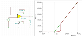
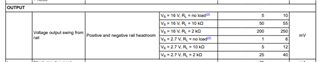
My customer wants to know the value of this with the condition of Vs=5V, RL=5kΩ~6kΩ. What will be max or typ. value for this?

Regards,

Ohashi

  • Also, does this "output swing from rail" changes with the output current condition, when it is sink current or source current?

    regards,

    Ohashi

  • The possible output voltages depend on the current; see figures 6-14, 6-15 of the datasheet.

    Is the behaviour the same if you make the rising voltage slower? It's possible that the model tries to simulate overload recovery (see section 7.3.7).

  • Hello Ohashi-san, 

    We have an entire training series on the input/output limitations on ti.com: https://www.ti.com/video/series/ti-precision-labs-op-amps.html

    Please share this resource with the customer to help with their understanding. 

    As discussed in the videos, the input limitation is the voltage common mode, for the TLV9152 it is specified 100mV above and below the power supply rail: 

    For the output limitation, this is usually a test condition in the AOL specification; these are not min/max values but rather a general rule, for the TLV9152:

    Looking at the values above, the output is unlikely to go closer than 100mV to the rail (including 0V). 

    Therefore, going back to the simulation, the unexpected output behavior happens due to the gain of 1 in which the input starts at V-. 
    Clemens is also right: 

    the model tries to simulate overload recovery

    Since the op amp output voltage is too close to the rail, the op amp simulation model might be acting in "overload." 
    There are two ways to fix this: 

    1. Change the input; Do not have the input go to V-. 
    2. Change V-; use a negative charge pump (such as LM7705) on the negative op amp supply rails to maintain linearity with signal levels near 0V.

    All the best,
    Carolina 

  • Hi all,

    Thanks for your support. Me and my customer got it.

    For figure 6-14, the voltage swing charactoristic is shown only for V+ rail. 

    When the op amp is sourcing the output current, assume that it is sourcing 80mA at 25℃,

    does the voltage swing of -3V applied only for V+, or is it also true for V- line? (means that there is a volatge swing of V- +3V too)

    If not, what would be the voltage swing for V- rail at above situation?

    Regrds,

    Ohashi

  • See figure 6-15:

  • Do you have a detailed charactoristic for figure 6-14 and 6-15 when the output current is around 1mA?

    Regards,

    Ohashi

  • Hey Ohashi-san, 

    What do you mean by:

    detailed charactoristic for figure 6-14 and 6-15

    Would lab data on a couple units 0mA to 5mA be enough? 

    All the best,
    Carolina

  • Hi Carolina,

    Understood that we don't have a magnified data for 6-14 and 6-15.

    Would lab data on a couple units 0mA to 5mA be enough? 

    That kind of data helps a lot! Could you kindly support this ASAP?

    Regards,

    Ohashi

  • Hey Ohashi-san, 

    Sure! I will on getting this data by end of week, 06/02 end of day Dallas Time. 

    All the best,
    Carolina 

  • Hello Ohashi-san, 

    Looks like we have run into some unexpected problems with our equipment, would end of day 6/9 be acceptable for the customer? 

    All the best,
    Carolina

  • Hi Carolina

    Got it that it will be delayed.

    6/9 is acceptable. I will explain it to the customer 

    Regards 

    Ohashi

  • Hello Ohashi-san, 

    Good news, our equipment complications have been resolved. Attached is a ppt that you may share with the customer of 4 devices (8 channels total) of data. 
    The vertical axis is relative to the supply rail (single supply 5V). 

    TLV9152 Output Voltage v.pptx

    As a reminder to the customer, this is small sample data and not characterization data. At the end of the day this is provided to the customer for convenience purposes. 

    TI assumes no liability for applications assistance or customer product design. Customer is fully responsible for all design decisions and engineering with regard to its products, including decisions relating to application of TI products. By providing technical information, TI does not intend to offer or provide engineering services or advice concerning Customer's design. If Customer desires engineering services, the Customer should rely on its retained employees and consultants and/or procure engineering services from a licensed professional engineer (LPE).

    All the best,
    Carolina