This thread has been locked.

If you have a related question, please click the "Ask a related question" button in the top right corner. The newly created question will be automatically linked to this question.

INA226: Current Measurement

Part Number: INA226

Hi,

We are using a number of INA226s in our design to measure the currents.

The INA226 datasheet provides details on how to calculate the Current_LSB (Current_LSB = Max Expected Current/2^15), and use that in the Cal Reg (CAL = 0.00512/(Current_LSB*RShunt) to set up the device.

The INA226 evaluation board user guide also gives the range of the Current_LSB, Max Expected Current/2^15 ≤ Current_LSB ≤ Max Expected Current 2^12.

On our design, we’ve set Current_LSB = Max Expected Current/2^15. However, when measuring currents <0.5A, the results don’t match the expected values. When Current_LSB = Max Expected Current/2^12, the measured current is closer to the expected value.

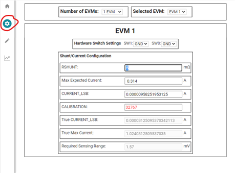
For example, with Max Current of 0.314A and Max current/2^15 = 9.58uA, the current is reported as 0.096A. Using Max Current/2^12 = 76.6uA, the reported current is 0.313A.

As another example, with Max Current of 1.775A and Max current/2^15 = 54.17uA, we get a reported current of 1.704A. Using Max Current/2^12 = 433.35uA, the reported current is 1.705A.

Why is there such a large discrepancy between the measured and expected currents depending on the LSB value? It also looks like the accuracy is dependent on the magnitude of the measured current, is that the case?

  • Scott,

    It also looks like the accuracy is dependent on the magnitude of the measured current, is that the case?

    Other than the quantization error due to the different LSB sizes I would not expect any change in accuracy from changing the configuration register.

    Why is there such a large discrepancy between the measured and expected currents depending on the LSB value?

    For the second set of values you reported (1.704A and 1.705A) you may need to calculate the real LSB value from the value you programmed into the calibration register. This is because the calibration register only has 15 bits of precision, so the current LSB may be truncated when you program it into the actual device. This might account for the small differences you are observing there.

    For the larger differences I would suspect that there is some configuration problem happening, but it is difficult to determine the source of the problem without more information. Could you read back the configuration register (to ensure it is written probably) and post that as well as the value of the shunt voltage register and what shunt resistor you are using to make these measurements?

    Thanks,

    Levi DeVries

  • Hi Levi,

    Thanks for your response.

    I have read back the configuration register with the low LSB (Max current/2^15) and high LSB (Max current/2^12) and both are 4127.

    low LSB shunt voltage register = 0278

    high LSB shunt voltage register = 0277

    The shunt resistor used is 5mR

    Also thought it would be worth adding the calibration register for both:

    low LSB calibration reg = 7FFF

    high LSB calibration reg = 342E

    If you need any more details just let me know.

    Thanks

    Scott

  • Scott,

    If you check the INA226 datasheet's register section you can see that the maximum size of the calibration register is actually 0x7FFF, so when you program the calibration register you are most likely hitting a size limit and not noticing. The true low LSB will be 0.00512/(0x7FFF * 0.005Ω) = 31.25µA and the current you measured should be calculated as 0.313A.

    You are hitting this limit because the current you are trying to measure divided by the range of the device's resolution is smaller than the resolution the device can actually handle. The smallest possible LSB for the device while using a 5mΩ shunt will be 31.25uA. If this isn't enough for your application, you can increase the resolution by increasing the size of your shunt resistor.

    A good resource as you run calculations to find the LSB and Cal values is the INA226EVM Rev. B GUI, which can automatically calculate your values based on your shunt and current requirements and will also warn you about things like exceeding the device resolution or range. Just use the configuration tab and enter a random device address (it doesn't matter for the calculator itself). 

    Let me know if you have any more questions,

    Levi DeVries