Part Number: OPA593
Other Parts Discussed in Thread: OPA541
Hello!
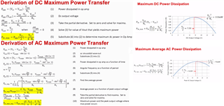
Tj max calculation formula
It is about the formula described in the section 8.4.1.1 Thermal Considerations of the specification.
I would like to confirm the parameters used to calculate the PDL.
I think that it is substituted into the formula of P=VI=V^2/R
Where did the parameter "4" in PDL=22.5^2V / (4 * 600Ω || 11.47kΩ) come from?
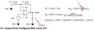
"22.5V" is V+(45V)/2 because the sentence says "the PDL is at a maximum when the output is fixed at a voltage equal to 1/2 of either supply voltage"
"11.47kΩ" is R1(1.47kΩ) + R2(10kΩ)
"600Ω" is RL
I just didn't understand the "4".
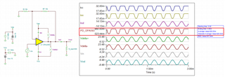
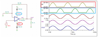
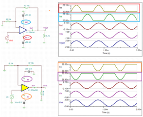
Also, in the circuit in Fig. 8, could you tell me how to think about power under the following conditions?
Power supply: ±15V
Gain: 2 times (R1=R2=10kΩ)
Input: AC3Vrms@3kHz
Output: AC6Vrms