This thread has been locked.

If you have a related question, please click the "Ask a related question" button in the top right corner. The newly created question will be automatically linked to this question.

XTR117: No 4-20mA output Current

Part Number: XTR117
Other Parts Discussed in Thread: INA321, LM317, INA823, XTR115, XTR116, XTR111

0081.pdf

Dear Team 

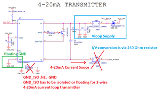
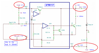
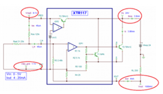
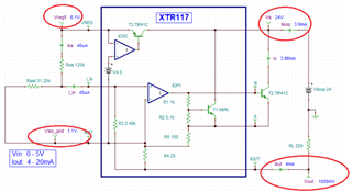
I have designed the 4-20mA transmitter using XTR117(transmitter) and INA321(amplifier)

I am facing issues in this particular design, attached the design file.

1) I am not getting the Output current as expected the maximum current i am getting is 0.300mA at Vout which we measured using the 4-20mA calibrator, transmitter is not even crossing 1mA current.

2) The XTR117 is getting over heated with the transistor attached.

3)XTR117 is consuming lot 50mA @ 12V and 24V.

4) At R8 and C6 the Output voltage is not crossing 600mV, in-between the R7 and R8 the voltage is getting varied in respect to the input.

  • Hi Yuvakumar ,

    1) I am not getting the Output current as expected the maximum current i am getting is 0.300mA at Vout which we measured using the 4-20mA calibrator, transmitter is not even crossing 1mA current.

    There are number of typos in the schematic, I would need to understand what you are trying to do. Please see the markings below. 

    Your application is similar to the application note. Please go through the note, and please ask questions if you are confused. 

    https://www.ti.com/lit/ug/slau526/slau526.pdf?ts=1689715062048&ref_url=https%253A%252F%252Fwww.google.com%252F

    Below is the XTR117 2-wire 4-20mA current loop simulation. 

    XTR117 E2E 07182023.TSC

    Do you have the H2 sensor's datasheet. I'd like to know how much current it will be used in the analog front end. 

    I have many questions. For instance, you implemented TVS at the input. Are you trying to protect the Vloop supply or protect against the transient condition between Vloop and current return lines? What is FB2 ferrite's DC impedance?  What is the purpose of LDO for, which the LM317's quiescent current is operated between 3.5mA to 10mA? 

    Please provide me with the H2 sensor's current consumption, perhaps I can simulate the whole schematic in Tina. With XTR117 2-wire 4-20mA current loop design, the total input current shall not exceed 3.7mA when there is no input signals. If you design consumes more current than 3.7mA under no input signal conditions (from the Vloop supply), then we have to find alternative ways to design the current loop transmitter. 

    https://www.ti.com/lit/ug/tidudf6/tidudf6.pdf?ts=1689716518753&ref_url=https%253A%252F%252Fwww.ti.com%252Ftool%252FTIDA-01504

    Best,

    Raymond

  • Hello Raymond,

    1) DO I need to isolate the GND_ISO and GND?

    2)If I isolate the GND and GND_ISO wont the Transmitter have the ground reference issue?

    3)If I remove the GND and GND ISO the internal regulator 5V reg VREG isn't generating the Voltage due to the ground reference it is showing the floating voltage and the Hydrogen Sensor will also not get any ground reference.

    4) IRET need to be floated? Shouldn't I need that to be connected to the Bridge network?

    5) The Ferrite beads are removed as of now and shorted the path directly so no FB's in the path

     6)This is just the transmitter design we have separate receiver design which has the 250E resistor network.

    7)I have attached the Hydrogen sensor datasheet

     tgs6812-d00_product_information(fusa)_rev05 (1).pdf

    8) I have implemented the TVS diode to protect against the transient condition between Vloop and current return lines.

    9)LDO is implemented to Supply the power to the Hydrogen sensor since its current consumption is around 175mA.

    10 The Current Consumption of the LDO referenced to the hydrogen sensor is very low but still if i connect the sensor the LDO is also getting heated abnormally. Only Hydrogen sensor is connected to the LDO.

    11)Instrumentation amplifier is Connected in transmitter to source the 5V reference voltage.

    Kindy look into this and let me know.

  • Hi Yuvakumar ,

    Without addressing your questions directly, here is how XTR117 should power the rest of the H2 sensor and Instrumentation amplifier (IA). I used INA823 instead because I had this example available in simulation. We can use INA321 as well, since this is low power IA. 

    H2 Sensor with INA823.TSC

    You need to calculate the total current budget for XTR117. Since the design uses multiple voltage references, you may consider to use XTR115/XTR116/XTR117 as the 4-20mA current loop transmitter. The current consumption calculation is the same. 

    The above simulation is an example to demonstrate how XTR should power the analog front end in 2-wire transmitters. The simulation is working, but it is not optimized, so there are things that are required to be finalized.

    We can address the input protection circuitry, EMI rejection and IA implementation separately once the issues of the analog front end circuitries are resolved. 

    BTW, I noticed that H2 sensor has a heater element. The heater may have to be powered differently from Vloop to GND, which is not the part of 4-20mA current loop. In other words, you can use LM317 to power the H2 heater with respect to GND in a different control block.  

    Best,

    Raymond

  • Dear Raymound

    1)Do I need to Separate the ground of LM317 to power the Hydrogen Sensor?

    2)If I isolate LM317 and Hydrogen sensor ground the INA321, VIN+ and VIN- will encounter two grounds at this point, how can I connect the VIN+ and VIN- without issue and any suggestions for isolated instrumentation amplifier with same pin out ?

    3) But the TVS diode around the 24V GND is also getting heated what could be the major cause?

    4)What could be the cause for the LM317 heating?

  • Hi Yuvakumar ,

    1)Do I need to Separate the ground of LM317 to power the Hydrogen Sensor?

    You are unable to use LM317 to power H2 sensor detector. There is a heater coil mentioned in the datasheet, which it draws 175mA  and I do not know where and how the heater circuit is used for the detector.  

    You have to make sure that the XTR117 or XTR116/XTR115's current budget is < 3.8mA when there is no H2 concentration or zero signal. All the loop current is supply by Vloop, which it can not exceed >3.8mA for the 2-wire current loop design topology. Else you may try XTR111 3-wire current loop transmitter. 

    2)If I isolate LM317 and Hydrogen sensor ground the INA321, VIN+ and VIN- will encounter two grounds at this point, how can I connect the VIN+ and VIN- without issue and any suggestions for isolated instrumentation amplifier with same pin out ?

    For XTR117 2-wire transmitter to work, only one GND reference is allowed, which is located at Vloop supply. All other floating ground are reference to IRET node. I have simulated and suggested the working conditions for the scenario, and please check out the simulation. 

    3) But the TVS diode around the 24V GND is also getting heated what could be the major cause?

    The proposed TVS (SMAJ36CA) is bidirectional and the clamp voltage is rated up to 40V, and it should not have current flow at Vloop = 24Vdc. If the TVS is damaged for some reasons or has lower clamp voltage, then it may not work for 24Vdc supply. Please check with conductivity meter. It should not heat up. 

    4)What could be the cause for the LM317 heating?

    If LM317 is draw too much current, it will cause heating. This is linear regulator and the power dissipation is (24Vdc - 3.0Vdc)*Iout = 19*Iout. If the H2 sensor is drew  175mA, the power dissipation is 19V* 0.175A = 3.325W.  

    If the H2 sensor is drawing 175mA of current, then you are unable to use the existing design schematic for 2-wire current loop transmitter. You may have to use other design approach. 

    You mentioned that H2 sensor does not draw much current, thus I put the XTR117 simulation together for your reference.  

    If you have other questions, please let me know. 

    Best,

    Raymond 


  • I have tried to remove the H2 sensor and the Regulator even though the XTR117 transmitter is getting hot and consuming 22mA @ 12V.

    I came across things like even if the Sensor is not connected due to the 40uA current at IN in the transmitter it should show 4mA but i am not getting that any rectification can be done in this ?

  • Hi Yuvakumar ,

    even if the Sensor is not connected due to the 40uA current at IN in the transmitter it should show 4mA but i am not getting that any rectification can be done in this ?

    Here is what I would do. 

    1. Please ultrasonic the PCB in DI-water for 15-20 mins. 

    2. Thoroughly rinse off the board and dried off the PCB, and baked in an oven at 85C for a few hours until all water moisture is evaporated. 

    3. Connect the PCB in XTR117 as shown in the configuration below. You should get the following voltage and current measurements. Use DMM's current meter to measure the current. I have sent you the XTR117 simulation previously and try to match the PCB V&I measurement with the simulation. 

    4. If you still see overheating issues, please desolder and remove the existing XTR117 and replace it with new one and clean off the excessive flex, and try it again. 

    There are handful of external components in the above configuration, and it should be easy to troubleshoot. 

    BTW, Ros = 125kΩ and Rset = 31.25kΩ should be precision resistor, 0.1% to 0.5% resistors in tolerances.

    Please send me the image of the XTR117 section of the PCB, if you overheating issues persists.

    If you have other questions, please let me know. 

    Best,

    Raymond 

  • Hi Raymond,

    I have made the connection similar to the image represented still the heating issue isn't resolved.

    2) With the above method the Vreg behaviour is abnormal, When Vin(Vloop) = 5 the Iout is 4mA when the Vin voltage is increased to 9V the Iout is 22mA its varying respect to the Vloop supply.

    3)Till Vin =12 no heating issue is found if increased to above 15V the Transmitter is heating abnormally and the IOUT is also keep on increasing with input voltage.

    4)Vreg need to stable but its varying respect to the input voltage, i get Vreg = 3.1V at Vloop = 24V

  • Hi Yuvakumar,

    2) With the above method the Vreg behaviour is abnormal, When Vin(Vloop) = 5 the Iout is 4mA when the Vin voltage is increased to 9V the Iout is 22mA its varying respect to the Vloop supply.

    BTW, the XTR117's Vloop supply voltage is 7.5Vdc minimum. So Vloop = 5V is invalid voltage. Vloop = 9Vdc is ok. 

    4)Vreg need to stable but its varying respect to the input voltage, i get Vreg = 3.1V at Vloop = 24V

    Could you measure the voltage nodes below (circled in red nodes) with Vloop = 24Vdc and let me know? Please make these voltage measurement with respect to GND. 

    How the Vreg = 3.1V is measured at Vloop = 24Vdc? If it is measured with respect to Iret node, then the IC may be damaged. You will need to remove and replace it. Please also send me an image of your XTR117 PCB.  

    Best,

    Raymond

  • Hi Raymond,

    I won't be able to share the PCB here i have posted that in a private message please check and let me know.

  • Hi Yuvakumar,

    I read your private message. Please provide me the voltage measurements with respect to GND in the basic XTR117 configuration. Then I may be able to tell you why it has no current output.  

    If XTR117 is damaged for some unknown reason, it will be good to replace the part and make the following voltage measurement. 

    Best,

    Raymond