This thread has been locked.

If you have a related question, please click the "Ask a related question" button in the top right corner. The newly created question will be automatically linked to this question.

TLV7022: Converting SINE+COSINE waves from AMR Speed Sensors into High Amplitude Square wave

Part Number: TLV7022
Other Parts Discussed in Thread: SN74LVC2G17, TLV9032, TLV3202, TLV9034, TLV7011, TLV7012

Dear TI Community,

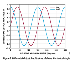
We are currently developing a low-cost condition-based monitoring system that involves measuring the vibration, current, and speed of equipment parts. Our focus is on integrating the ADA4570/71 AMR Speed Sensor into the system to accurately measure shaft speed.

To convert the AMR sensor's SINE and COSINE waves into square waves, we are exploring a Comparator-based design instead of an ADC-based approach. These square wave signals will be fed into the Quadrature Encoder Interface (QEI) of the STM32G474 MCU. The distance between the sensor and the MCU is 1m, and we plan to use a standard 24AWG STP cable for connectivity.

We kindly request your expertise and guidance in providing a reference design that optimizes cost while ensuring reliable and robust performance for this application. Specifically, we seek recommendations for suitable filters, hysteresis settings, and any additional measures to enhance the solution's performance.

Our approach involves considering the following:

Use of the TLV7022 comparator for zero crossover detection and triggering.
Installation of SN74LVC2G17 Schmitt triggers at the MCU end to improve signal quality.
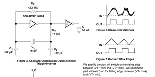
Exploration of the direct use of the Schmitt Trigger SN74LVC2G17 for converting the SINE wave into a square wave.

We have the following specific questions:

  1. Is the use of a Schmitt trigger to convert the SINE wave into a square wave a reliable solution?
  2. Considering our 1m cable length, can we use two sets of Schmitt triggers (one at each end) to minimize the impact of noise? Are there any potential design considerations we may have overlooked?
  3. What additional passive circuitry would be required for the output signals from the ADA4570 or ADA4571 (differential or single-ended signals) into Square waves?
  4. Do you have any additional suggestions or guidance based on your experience in similar applications?
  5. We kindly request your insights on the most optimal Comparator-based Zero-crossover solution that allows for the reliable transfer of a 0-5V square wave over a 1m distance from the sensor to the MCU.
  6. Furthermore, we are interested in understanding the potential benefits of incorporating Schmitt triggers at the MCU end to enhance signal quality.

Thank you in advance for your valuable assistance in addressing our query. We greatly appreciate your expert recommendations and suggestions.

Best regards

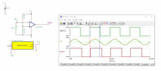
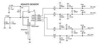
Sensor Output Schematic:

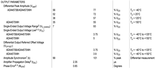
Differential Signal specifications:

Best regards,

  • Hi Shreeneet, 

    Thanks for reaching out. I saw that the ADA4570 datasheet mentions these output signals are biased around a common voltage of VDD/2. If that is so, then you could create the reference of VDD/2 on the inverting input of the comparator and then have the cos/sin signals on the non inverting input. TLV701x/2x could be a decent option but I would actually recommend the push pull comparator TLV9032 (dual) or TLV9034 (quad) as this provides much better precision and speed. External hysteresis would be recommended but I would be careful as you do not want any caps on the noninverting node of the comparator because they would add a delay and negative the effect of the hysteresis, so C5, C6, C7, C8. We also have TLV3202 which is also even faster and has internal hysteresis. 

  • Hello Chi,

    Thank you for the suggestions. We are looking for a cost-optimized solution, TLV3202 is fairly costly for our use case, are there cost-optimized Comparators with Push-Pull & internal hysteresis? We found TLV7011 to be within the cost budget, is it equally suitable for our use case?

    Also, can we use a simple Schmitt trigger logic converter to convert the SINE wave into Square waves? Is this idea too theoretical for practical implementation in our use case? We have to transmit the Square wave across a 1m to 2m long cable in an industrial environment. Something like SN74LVC2G17 at both ends of the cable is suitable for our budget & might reduce the BoM requirements. Can you guide us in this direction, if we are missing something obvious with this approach?

    Also, would we need differential signaling instead of 0-5V square wave for a 2m distance assuming we are using Shielded Twisted Cables to minimize the noise pickup in the cables?

    Regards.

  • Hi Shreeneet,

    TLV7012 (dual push pull) should be ok for this application. I only recommended TLV903x and TLV3202 as they have better speed capabilities and accuracy which would be helpful in terms of phase lag and duty cycle of the waveforms. TLV9034 is also available in quad package. 

    I think a comparator is better suited instead of a schmitt trigger as you can set the reference to be at the exact mid point to get the right 50% duty cycle. Just looking at that SN device, the threshold trigger point would be 2.2V-3.7V at a VCC = 5.5V. With a comparator there is just more control and ability to get the accuracy of the square wave output. 

  • Hello Chi,

    Our square wave signal shall never be more than 200Hz in frequency, yes having ~50% duty cycle shall be essential.

    Do you think we still need precision Comparators for this use case? Also, shall Schmitt triggers be useful for our application given the low-frequency signals? Using the Schmitt trigger simplifies the design & cost drastically.

    Also we are fairly new to Analog Designs, can you help us with a appropriate reference design with filters & ESD suggestions in the circuit that we can further analyze, understand & build upon our final circuit for this use case?

  • Shreeenet,

    If 50% duty cycle is essential, then Im not sure how that schmitt trigger part could be a good fit. As I mentioned, it is difficult to tune and control the schmitt trigger to be at the mid point of your signal. See the simulation below. As you can see, the duty cycle at the output of the SN part is not 50% duty cycle and theres some phase lag as well introduced. I still think comparators are a better approach. 

    This is the closest reference design I could find: ti.com/lit/ug/tidua05a/tidua05a.pdf?ts=1689957531034&ref_url=https%253A%252F%252Fwww.google.com%252F

    Sinwavetlv7012.TSC

  • Hello Chi,

    As per your insightful suggestion, we would be using TLV7012 for our use case. Being a cost-sensitive application, can you help us understand the impact of 1% tolerance resistor pair vs a 0.1% tolerance resistor pair in this use case?

    We need to maintain a constant phase angle between both the square waves & for direction sensing, while for frequency sensing, a generous tolerance is acceptable. Kindly guide us with any ESD protection that may be required along with an LPF filter for this use case where the maximum frequency may be 300Hz so a filter to attenuate beyond 600Hz shall be suitable.

    Kindly guide us to make this robust circuit for implementation.

    Regards.

  • Hello Shreeneet,

    The tolerance of the resistors will affect the accuracy/timing of the circuit so the lower tolerance will mean less deviations from the targeted value of the reference that you are transitioning through (assuming you're using a resistor divider to create the reference).

    I do not know much about designing external esd protection circuits as that is outside of my expertise. Here is a resource that may help you: ESD Protection Layout Guide (Rev. A)

    For LPF, you could use a 10kohm resistor and 26.nF cap.