This thread has been locked.

If you have a related question, please click the "Ask a related question" button in the top right corner. The newly created question will be automatically linked to this question.

LM358B: Abnormal waveform

Part Number: LM358B
Other Parts Discussed in Thread: TLV9102, TLV9302

Hi team,

I am Mitsubishi FAE Lillian, nice to meet you~

Now we met an issue when use LM358BIDR in elevator application need your support.

 Please specify: 1. Is this phenomenon normal? 2. Under what conditions does this phenomenon occur? 3. How to improve?

When Mitsubishi recently investigated the problems of mass-produced driver boards, they found the following phenomena. Many elevators have this phenomenon fail probability>90% , so Mitsubishi R&D considere this is a common problem. Please help analyze the reason, thank you!

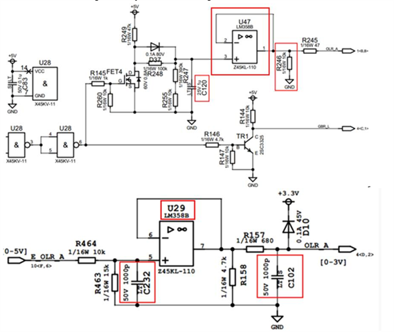
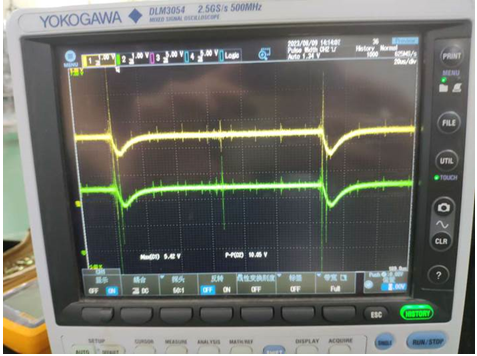
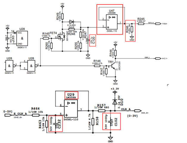
In the schematic diagram below, when the traction machine (motor) is running, the waveforms of C120 and C260 are normal, the waveforms at both ends of R246 will drop to 0V abnormally, and the waveforms at both ends of C102 will drop slightly.

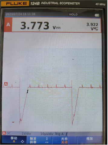
The drop width is 10us, and the occurrence period is 62.5us (16KHz). The PIM module is driven at the same frequency (8KHz), and the frequency of abnormal drop occurrence is consistent with the on-off frequency of the module, which coincides with the rising and falling edges of on-off.

U47 and U29 are TI's LM358BIDR operational amplifier chips. After replacing them with chips from other manufacturers, the abnormal drop disappeared.

Or connect a 1nf capacitor in parallel with R246, and the drop will disappear.

(OLR_A is connected to E_OLR_A through the DM plug-in in the figure below, and the waveform at both ends of R246 does not change when the plug-in is disconnected)


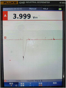
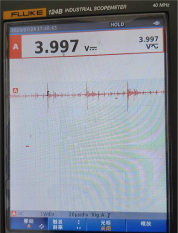
Normal waveform: DC voltage with 16KHz interference


Abnormal waveform: DC voltage, with 16KHz abnormal drop, 10us width, will cause MCU misjudgment;


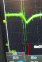
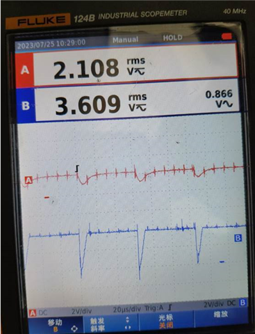
Abnormal waveform: The waveform of one of the elevators C120 dropped slightly


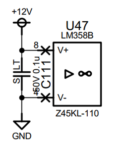
In addition, U47 and U29 are all use 12V supply.

Thanks

Lillian

  • Lillian,

    4V input and output works with the 12V supply. 

    Output drops of 2V are normal if the output load current changes quickly. 4V drops are not normal. See application note to know why. Design Guidelines for Devices with LM324/LM358 Cores

    With a 4V DC output and 10k load the ground. R246 current is 400uA to ground ; there is also an internal (roughly) 120uA sink for a total sink of 520uA. Output pulses are negative, so PNP sink driver must normally be on (more importantly Darlington NPN off). That means R245 is supplying over 520uA for that to be true. If the "thing" on far side of R245 suddenly goes lower than 520uA and voltage probably below ground, then the sink PNP becomes off. Now the output voltage can drop 2V before the Darlington NPN starts sourcing current. 

    I'd like to see voltages on both sides of R245. I expect right side to change by more than 4V.

  • Hi Ron,

    ​The right side of R245 "OLR_A" is connected to the "E_OLR_A" R464.

    ​Once we cut off the  plug-in  of  "OLR_A", then the right of the R245 is open . The wave of the R246 is also the same.


    Ammend: the attachment's ' Slight drop ' wave is the C102, not the C120.

    Do you have other comments with this issue?

    Thanks

    Lillian

  • Lillian,

    4V on the C102 node will strongly forward bias D10 because resistance is only 680 ohms. 

    What are the waveforms on pin 5 and 3.3V supply?

  • Hi Ron,

    We have measured the +5V-GND, +3.3V-GND, and +12V-GND. They are all Stationary waveform without unexcepted dips.

        We do some test again today.(In the following schematic , the R245 is connected to the  R464).FYI.

    1) The wave of left and right point of R245 to the GND are the same.

    2)CH1(yellow):R246-GND; CH2(green):C102-GND

    3)CH1(yellow):C232-GND; CH2(green):C102-GND

    Thanks

    Lillian

  • Lillian,

    The waveform were vey helpful. I have figured out the problem. The output drops suddenly because pin 6 (and 7) have a transient voltage below ground. 

    I highlighted where C102 goes well below ground (off screen). LM358B is not phase reversal protected. This transient will pull output drive low very quickly and the recovery will happen at the natural slew rate. This matches the output waveform shape. 

    Pin 6 will also have a transient voltage below ground. 

    This can be solved by eliminating the below ground voltage transients or changing to an op amp that has phase reversal protection. 

  • Hi Ron,

    Thanks for your reply!

    So do you have pin to pin chip that has phase reversal protection recommend?

    Thanks

    Lillian

  • TLV9102, TLV9302.

    (Almost all modern op amps have phase reversal protection.)