This thread has been locked.

If you have a related question, please click the "Ask a related question" button in the top right corner. The newly created question will be automatically linked to this question.

TLV9002: Distortion in the Second-order Butterworth Bandpass Filter Circuit

Part Number: TLV9002

Hi ,

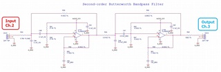
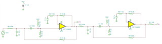
I hope this message finds you well. I wanted to reach out regarding the Second-order Butterworth Bandpass Filter circuit (kung_tlv9002.TSC) that you assisted me in designing around five months ago. You can find the original discussion we had on the TI E2E Amplifiers Forum at this link: https://e2e.ti.com/support/amplifiers-group/amplifiers/f/amplifiers-forum/1207108/tlv170-butterworth-filter

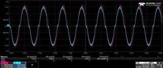
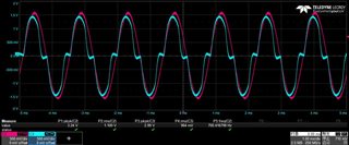
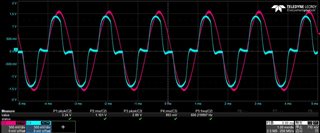
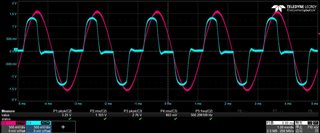
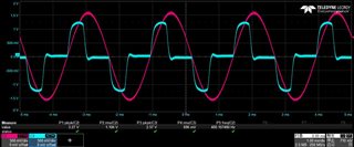
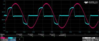
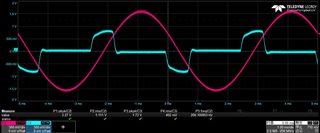
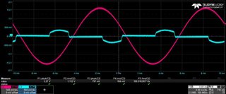
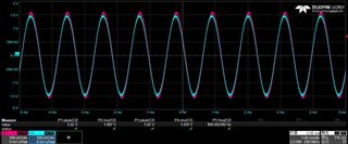
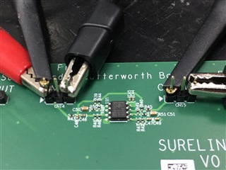
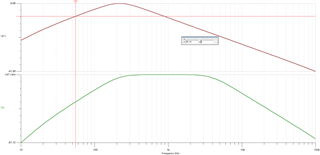
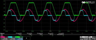
I successfully implemented the circuit on an EVB for testing purposes. However, I've encountered an issue with the output waveform. Specifically, there seems to be distortion occurring when the frequency is below 900Hz. I have attached a  Statistical Chart(Excel) and waveforms(JPG) for your reference.

I would greatly appreciate your expertise in addressing this problem. If you could provide guidance on how to rectify this distortion issue, I would be very grateful.

Thank you for your time and assistance.

Best regards,

Kungyeh

Distortion.xlsx

  • Hi Kungyeh,

    Just to confirm, the circuit you are testing is the exact same as the one in kung_tlv9002.TSC file? There are no value changes? 

    Best Regards, 

    Robert Clifton

  • Hi ,

    Thank you for reaching out.

    The only difference that I have implemented is changing the resistor value from 1.536kΩ to 15.4kΩ.

    Attached are the schematic and pictures of the EVB for your reference.

    Best regards,

    Kungyeh

  • Hi Kungyeh,

    It's not easy to see when looking at the final stage of the op amp. But when you look at what's happening at the first filter stage, you will see that there is some gain peaking happening on the signal. See the red curve below for the gain across frequency of the first stage versus the green curve for the output. 

    When you put a small signal through the circuit, there's no distortion since the gain will not violate the max and min the output voltage can go too. However when you put a signal through that is large enough, you will start railing the output at the first stage. This is what's causing your signal distortion. 

    Best Regards,

    Robert Clifton 

  • Hi ,

    Indeed, you are correct. The output waveform of the first filter stage is being clipped at 3.3V, as depicted in Picture Ch.4 with the green line.

    How to modify the schematic in order to align with the filter specifications?

    Your expertise in addressing this matter would be greatly appreciated.

    Best regards,

    Kungyeh

  • Hi Kungyeh,

    Well what are some of the requirements in the system? What is the maximum expected input signal? 

    Rail to rail signals might not be possible, so you might need to get a higher voltage supplies and change to a high voltage op amp. That's one option. 

    Best Regards, 

    Robert Clifton