This thread has been locked.

If you have a related question, please click the "Ask a related question" button in the top right corner. The newly created question will be automatically linked to this question.

TLV3201: Grid voltage sense with hysteresis

Part Number: TLV3201

Hi i want to sense grid voltage and cutoff operation with hysteresis band using TLV3201

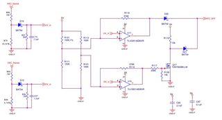
i designed with 185V ac ON and 175V ac off,Hysteresis band is almost 400mV

when i tried testing UV opamp alone,ON  happens at 210V AC and off happens correctly at 175V

help me to figure out the issue

Thanks in advance

  • Hi Venkatesh,


    Could you please provide a bit more information about the VAC_Sense signal (DC offset, voltage swing, frequency, etc.)?

    If possible, could you also include some scope shots of what you are observing? I’d like to know what nodes you are measuring and how you are measuring it in order to paint a more complete picture of what you are seeing.

    From my simulations, it seems like the switching thresholds VL and VH are 2.3V and 2.7V at the IN- input (UV_in). Could you confirm is this is what you want?

    From what I understand, it looks like you are using the Schottky diode to rectify the AC signal and charging the 2.2uF capacitor to settle at some voltage for the comparator to switch. Attached is a simulation that you can use to change the voltage swings of the VAC_Sense signal to see if the transient simulation settles at your desired voltage.


     venkateshbacgrid.TSC

  • Vac sense signal is coming from full Bridge rectifier(AC-DC) with c filter.Vacsense= sqrt(2)*Vac

    for 180V Ac,Vacsense=254V DC

    230VAC,Vsense=325V DC

    similarly 265VAC ,Vsense= 375V DC.

    yes Range of VL & VH is 2.3 & 2.7V only

  • Hi Venkatesh,

    I’m going to need more information. Could you please provide an oscilloscope screenshot of the inputs to the comparator (UV_in and the non-inverting input), the output of the comparator, and VAC_Sense (or R78 Voltage if VAC_Sense is too high) with you running your relevant tests? It’ll be helpful to see what the comparator is seeing in order to see why it isn’t switching according to your calculations.

    In addition, how are you testing the comparator? Are you applying an AC signal to your full bridge rectifier and gradually increasing the swing in order to see when the comparator switches on or off? If you have access to UV_in or the anode of D16, it would be helpful to apply a signal there to see when the comparator is switching. The discrepancy might be caused by the ripple at the output of the full bridge rectifier causing changes at the input of the comparator.


    Please send the relevant information so I can assist you further.

  • Hi HO SIU,

    i have probed Comparator +IN input,-IN input and Output of single comparator with Input Vac changed

    Vset voltage at (Pin 3) +IN

    Vactual voltage sensed voltage at VAC- 185V AC

    Pin 1 opamp output changed from 5V to 0V at VAC 197V AC

    Thank you

  • Hi Venkatesh,


    Thank you for the scope shots; these are very useful. From what you’ve sent, it seems to me that Vac = 185V is not causing the IN- voltage to reach the 2.8V necessary to cause the output of the comparator to switch from high to low. It’s also a bit concerning that the VH seems to be 2.8V instead of the 2.7V that we calculated. Since internal hysteresis and offset voltage are in the one millivolt range, VH should be dominated by variations in the 5V rail and the tolerance of the resistors. Could you try inputting a sawtooth signal from 0V to 3V at UV_in to see the switching thresholds of the comparator? Since we’re seeing a deviation from our calculations with VH, it would be good to check if there is a deviation in VL as well. Checking the actual resistor values of R111, R121, and R116 would also be useful.


    If VL actually turns out to be 2.3V, a solution that I would propose is that you change the external hysteresis to VL = 2.3V and VH = 2.6V in order for the comparator to switch at your desired AC voltages. Changing R121 to 105kΩ and R116 to 806kΩ while keeping R111 100kΩ should get you VL = 2.29V and VH = 2.59V. Could you try implementing the changes to the resistors to see if this causes the comparator to switch at your desired AC voltages?

  • Dear HO SIU,

    Good morning,

    It works well.I just changed R116 to 806Kohm,1Mohm,finally 2MOhm.

    I achieve Hyteresis loop band of 0.2V.

    Thanks for your support