This thread has been locked.

If you have a related question, please click the "Ask a related question" button in the top right corner. The newly created question will be automatically linked to this question.

TLV9352: Instrumentation amplifier with TLV9352 and TLV9351: unexpected output at negative input voltage

Part Number: TLV9352

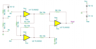
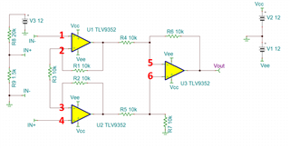
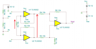
I've designed an instrumentation amplifier based on the 3 operational amplifiers topology as the following below. In the design, two op amps are implemented using TLV9352IDR and the third one is implemented with TLV9351QDBVRQ1. Both devices are supplied from +12V to -12V. 

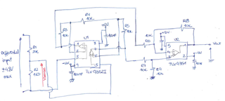
In this case, the input sense I have to sense is a differential voltage up to +/-48 Vdc and provide a proportional output up to +/-10Vdc. Sense voltage is made across R2 from input resistor divider R1-R2. When input is +/-48Vdc, R2 voltage is +/-3.3V and with the gain configured to 3, the output should be +/-10Vdc.

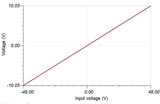
When input supply is positive, the instrumentation amplifier works correctly in the prototype. I've tried with input voltages of 5, 10, 24 and 48Vdc and output voltage results 1V, 2V, 5V and 10Vdc respectively. 

However, when input voltage is negative, the instrumentation amplifier only works for low input voltages. I've tried with input voltages of 5, 10, 24 and 48Vdc and output voltage results -1V, -2V, -2.3V and -4.7Vdc, respectively. 

Please, could you clarify me what is happening in the design? Have TLV9352IDR and  TLV9351QDBVRQ1 an input voltage limitation or clamping?

Thanks in advance.

  • Hello,

    I have simulated your circuit and did not see the issue, is it configured exactly as drawn? Also I have attached a simulation file if you would like to simulate the circuit configuration.

    TLV935x_INA.TSC

    Best,
    Jerry

  • Hi Jerry,

    thank you very much for your answer.

    Previous to the prototype, I simulated the design with the same results as yours. Additionally, I've reviewed the layout of the prototype and it is according to the electrical diagram. So I don't see any issue that could lead into my results. I've measured in several prototypes with the same result. 

    Could it be due to an internal clamp of TLV935x?

    Best regards

  • Hey AM,

    The input and output diode clamping behaviors of the TLV935x are modeled, so if something were going on there it would show up in simulation. Are you sure your negative rail is properly being generated? When you are inputting these negative voltages, are you able to probe the node voltages at each stage of the instrumentation amplifier?

    If you could provide an example of the node voltages when there is an improper output, this can help in debugging. Please also make sure to probe the voltages on both supply rails. Additionally, what is the load on Vout?

    Best,
    Jerry

  • Hi Jerry,

    At the beginning of the tests, I've measured the rails  of both devices obtaining +12Vdc and -12Vdc  but I did not measure them during the unexpected negative output voltages. 

    Both rails are generated using DPAN02B-12(Isolated DC/DC Converters - Through Hole 18-36Vin +/-12Vout +/-83mA) from Mean Well. Could this converter be not enough? Apart from this circuit, there are several circuits based on TLV935x to sense different voltage/current of the system  attached to DPAN02B-12 converter. For all amplifiers, I assumed that current consumption is IQ=850 uA.

    Maybe this converter is not enough for the system but it is very strange that only occurs at negative voltages. There are other 2 instances of the circuit above but they only sense positive voltages from 0 to 100 Vdc and both work properly. 

    I've tried the circuit without load at Vout. The output of this circuit will be connected to a PLC input module with 10kohm input impedance.

    Thank you for all your help..

    Best regards

    AM

  • Hi Jerry,

    I've measured the power supplies when the input voltage is negative and both supplies are +12Vdc and -12Vdc, without changes. So it seems that DC-DC converter is not the responsible of this situation.

    Thank you for your help.

    Best regards

  • Hey AM,

    Thank you for confirming the integrity of the power supply.

    Could you please probe the node voltages when you are inputting the negative voltages? When the improper output voltage is observed, please provide the voltage at each of the numbered nodes below. This can help us break down the system view and help us find out which stage is seeing an issue.

    Best,
    Jerry

  • Hi Jerry,

    By now I can provide you the measurements done in R3 and R4-R5.

    Meas point\Input +48Vdc -48Vdc +24Vdc -24Vdc +10Vdc -10Vdc +5Vdc -5Vdc
    VR3 (V) -3.35  1.56 1.68 1.67 -0.7 0.7 -0.34 0.34
    VR4-VR5 (V) -10 4.69 -5 2.3 -2.1 2 -1 1
    VOUT (V) 10 -4.7 5 -2.3 2.1 -2 1 1

    When I have the other measurements, I let you know.

    Thank you in advance

  • AM,

    It is clear that the difference amplifier stage at the end is working properly. To verify the function of the gain stage, I would need the input voltage values. (nodes 1 and 4 from the amplifiers)

    Please provide these node voltages referred to ground, not referred to each other if possible.

    Best,
    Jerry

  • Dear Jerry,

    Thank you very much for your help. By now I've not been able to measure to points you mentionend since I've been ill. When I have the values I let you know.

    Best regards.

  • AM,

    Sorry to hear that, I hope you are feeling better! I am looking forward to your feedback.

    Best,
    Jerry