- Ask a related questionWhat is a related question?A related question is a question created from another question. When the related question is created, it will be automatically linked to the original question.
This thread has been locked.
If you have a related question, please click the "Ask a related question" button in the top right corner. The newly created question will be automatically linked to this question.
Good Afternoon,
I'm wondering if someone can help me define the min and max of the settling times slew rate limits for the OPAx192 Op amps. There are typical shown but not the extremes.
We are using the amplifiers in a ADC circuit that we would like to know margins for our sampling times.
Thanks,
John Gray
John,
I will ask our model expert if there is a simple way to adjust slew rate on the OPA192 model. This may take a little time.
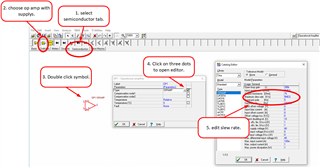
There is a very simple generic model that you can use to adjust many different parameters like slew rate. Depending on your needs maybe this is sufficient. Tina provides this under semiconductors. If you click on the model, then click on be three dots near "type", you can edit the parameters.

Best regards,
Art
John,
Below is the modified model. Inside the model, you can update the X_U31 instance line for different slew rate. Specifically, IPOS and INEG values by +/-15% of given value of 2.4A. Note that this number affects DC clamping blocks for both V, and I.
I hope this helps!
Best regards,
Art
Art,
I use Cadence Pspice software tools, so I didn't know where to use the .TSC file. Your explanation of where in the model to change the values allowed me to find it in the pspice lib files. I changed it and it worked. Thank you so much. I assume I can move the bandwidth around 15% to get small signal responses to change by 15%, I'll try that.
Have a great day!
-John Gray