This thread has been locked.

If you have a related question, please click the "Ask a related question" button in the top right corner. The newly created question will be automatically linked to this question.

PGA309EVM-USB: PGA309EVM-USB

Part Number: PGA309EVM-USB
Other Parts Discussed in Thread: PGA309,

Good morning,

i'm trying to use the PGA309EVM-USB with USB DAQ Platform and PGA309 Test board.

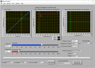
Making use of the USB_DAQ + PGA309EWM.ppt. i created a configuration file, disabling the sensore emulation.

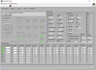
I connected a load cell, with a 350 ohm bridge and sensitivity of 2mV/V, to the PGA test board, and using the PGA309 Calculatore software, i found  Coarse offset, Front end PGA Zero DAC, GAIN DAC and ouput amp gain.

I enabled Internal Vref, to 2.5V, and Sensore excitation to 1.3V and VSA to 5V.

The PGA309 Test board configuration is in Vout 4 wire and the jumper settings are the following:

JMP4 ext

JMP5 ext

JMP13 DIODE

JMP6 ext

JMP7 nc

JMP8 one to prg

JMP3 ADS1

JMP9 nc

JMP1 nc

JMP17 ext

JMP 12 Vexc

JMP11 vdut

JMP10 nc

If i measure  Vref and Vsensor (usign a multimeter), i read 2.5 V and  1.28V, parameters that i set but i don't see Vout variation when apply a known weight on the cell.

Problably i'm doing something wrong, any suggestions?

Thanks in advance,

Carmelo

  • Carmelo,

    Before connecting your real-world sensor to the PGA309EVM, can you please try to use the sensor emulator.  Below is a step-by-step procedure on how to set the jumpers and what software settings are required to get a good calibration result with the sensor emulator.  Once you confirm that this works, we will know the hardware and software is working and we can debug your real-world sensor.

    0841.pga309EVM software step-by-step example 9-22-2023b.pdf

    Best regards, Art Kay

  • Good Morning Art Kay,

     I followed, step by step, the instructions on the pdf and obtained values close to the target of 0,5V and 4,5V but the column  Temp DAC reports always C2 at 0, 50 and 100 °C.

    When I run sensor emulator for verification Temp Sensor Output  is always 0V in different position of Temperature Slider, instead I see Out Meas variation but with a load of 100% I obtained an error of -13% (Out Ideal 4,49197, Out Meas 3,97229). Temperature compensation seems  doesn't work correctly.

    If i set the Load Slider at 64,4578%, Bridge Vexc input, Bridge Sensor Output and Absolute Bridge are close to the values present on the pdf.

    Is it possible an hw problem?

    A question about a real world sensor. Using a load cell, for example, of 20Kg with a bridge of 350 ohm and sensitivity of 2mV/V.

    If i set a range outoput value between 0,5V (0 Kg) and 2,25V (10Kg), if i load a weight of 20Kg on the load cell, the voltage output is blocked to 2,25V (because i configured so the PGA309) or the output voltage will be close to 4,5V?

    I bought the evaluation board to do this test.

  • Carmelo,

    I think I understand the issue.  The software requires US regional settings (i.e. period instead of comma for decimal point).  I believe at some time in the past this software was tested with European regional settings, but perhaps the latest version of windows has a difference that impacts the operation.  In any case, I ran the software with US regional settings and got good calibration results, and then I changed my regional settings to Germany and got similar results to what you see (i.e. TEMP DAC is constant).  The attachment below summarized this test.  I know it is inconvenient, but can you please try the to change your regional settings and re-run the test.

    pga309-regional settings.pdf

    Best regards, Art Kay

  • Good Morning Art Key,

    I modified Region and Regional format as explained in the pdf and there was the same error in the temperature output.

    Instead, after I modified  in Customize format window the parameter Decimal Symbol changing the comma value with the point value.

    After that, the board, configured in emulation, works correctly.

    The board works but i have always the problem using a real worl sensor.

    Is there any document that explains the setup with a real world sensor?

    Regards,

    Carmelo

  • Carmelo,

    Can you tell me the information for your sensor as shown below?  Are you using the PGA309EVM for this test?  Assuming you are using the EVM, and you provide the sensor information below, I can do a step by step calibration with the sensor emulator configured to match your sensor. The items shown in red in the table below are examples.  Please fill in those fields with your specific configuration.  Once you do this, I will document each step in the calibration procedure.  I think your real world calibration is likely failing because of a jumper setting or software configuration issue.

    Temp Sensor type

    Diode


    Number of temperatures in calibration

    3, -25C, +25C, and +125C


    Are you correcting for linearity versus pressure

    Yes


    Output configuration

    4 wire voltage output


    Temperature

    Temp Sensor Voltage

    Sensor Minimum

    Sensor Maximum

    -25C

    0.6V

    1mV/V

    10mV/V

    +25C

    0.65V

    1.6mV/V

    9.5mV/V

    +85C

    0.75V

    0.3mV/V

    11mV/V


    Temperature

    Sensor Min

    Sensor Mid (50%)

    Sensor Max

    +25C

    1.6mV/V

    6mV/V

    9.5mV/V

  • Good Morning Art Kay,

    as first step, I'm trying tests in 4 wire voltage ouput, in second step I'll try to test the current output.

    Now I'm using a load cell with a Wheastone bridge of 350 Ohm with a sensitivity of 2mV/V, with 2.5V Vref internal and of 1.3V of Vexc, I'm testing the sistem at 25°C

    I resolved my problem, I searched and read, in this forum, a lot of post regarding the PGA309EVM and I found an old post of yours

    https://e2e.ti.com/support/amplifiers-group/amplifiers/f/amplifiers-forum/49904/pga309-usage/742652?tisearch=e2e-sitesearch&keymatch=PGA309EVM-USB#742652

    where You explain that using the block diagram Tab for a real world sensor, the Test Pin box have to be checked otherwise the registers will be over written by the EEPROM.

    I didn't find this information in the software manual.

    Checked the box, now I'm able to make work the board with my sensor in Voltage Output configuration. After this tests, I'll try to work in current output.

    Thanks for the support,

    Carmelo

  • Carmelo,

    Happy to help.  Feel free to reach out if you have further questions.

    Art