This thread has been locked.

If you have a related question, please click the "Ask a related question" button in the top right corner. The newly created question will be automatically linked to this question.

INA143: Gain smaller than 1?

Part Number: INA143
Other Parts Discussed in Thread: ADS1284, PGA281, INA145

Hi to all!

I'm trying to design ADC with variable full scale, so I need selectable variable gain stage (attenuator).

In this discussion it was explained how get gain different than 10 (smaller than 10, bigger than 1).
https://e2e.ti.com/support/amplifiers-group/amplifiers/f/amplifiers-forum/936115/ina143-can-i-make-the-gain-of-ina143-smaller-than-10?tisearch=e2e-sitesearch&keymatch=INA143#


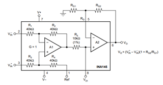
So I supposed to use INA143 to reduce amplitude (instead using G=0.1 and further gain in a second block, to make noise com
What about gain smaller than 1?
I need selectable gains:
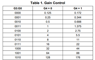
- x0.125
- x0.250
- x0.350

Can I simply add series resistors (0.1%) to inputs, such in discussion above? (e.g. 25kOhm 0.1% resistors for gain=0.35)
Is there a suggested way to select resistors (such an alanog switch/mux)?
Thanks.

  • Hi Michele,

    I believe the post you referenced is considering INA143 configurations for a fixed gain application. If you require selectable gains, you may consider using a programmable gain amplifier (PGA) as this will offer the best performance, flexibility, and gain accuracy.

    What are your bandwidth requirements? Are you intending to drive the ADS1284 with this attenuating gain stage? I see the ADS1284 is a 4kSPS ADC.

    In this case, I recommend the PGA281 which is optimized for high-precision low-frequency applications. The PGA281 has digitally-selectable gain settings with 0.125, 0.25, and 0.344 gain options. It is also fully-differential so it can be configured to directly drive your differential ADC as shown in the configuration below.

    https://www.ti.com/product/PGA281?keyMatch=PGA281&tisearch=search-everything&usecase=GPN-ALT 

    See PGA281 Datasheet

    There is another similar version of this device, PGA280, which is controlled via SPI and has an integrated input multiplexer.

    As you can see from figure 16 of the PGA281 datasheet, the lowest gain setting begins to roll-off at frequencies higher than ~10kHz. If you require AC precision at these higher frequencies you may consider a wide-bandwidth fully-differential PGA such as the new PGA855

    Regards,

    Zach

  • Thanks, I'll evaluate PGA such 281 for gains above.
    At same time my colleagues would a more flexible design for non-standard transducers where my pre-amp would act as amplifier/attenuator.
    We are also designing board for ADS1821 due we already have evaluation board for this.
    Bandwidth is not a problem due overall sampling rate would be 200SPS, so ADC will sample below 4000 SPS.

    We are also evaluating different way (I don't like this but it could be useful to make noise comparison):
    use INA145 adding 360K resistors to pins 2 and 3, to get G1=0.1, then use digital pot as RG1/RG2 to create variable A2 gain.

  • Hi Michele,

    If you require both amplification and attenuation, the PGA281 is an excellent choice as it offers binary gain steps from 0.125 V/V to 128 V/V with an additional gain scale option of 1.375 for each gain setting.

    I agree that adding 360kΩ resistors to INA145 inputs for attenuation is not optimal for the reasons described below.

    1.)  The on-chip precision 40kΩ resistors are laser-trimmed to achieve accurate gain and high common-mode rejection as well as excellent TCR tracking to ensure high precision over the temperature range. The tolerance of your 360kΩ input resistors will produce a source-impedance mismatch between the INA145 inputs that will reduce the gain accuracy and CMRR performance of the INA145.

    2.) An attenuate-then-gain scheme will greatly reduce the noise performance when you configure the INA145 in gain. For example, if the total gain of the INA stage to equal 1, the noise gain must be equal to 20dB as you have attenuated the input voltage by 20dB. Furthermore, the thermal noise of the large 360kΩ resistors will also be amplified by the noise gain.

    3.) The 1/f low-frequency noise of the PGA281 is significantly improved compared to INA145 as the PGA281 uses the auto-zero topology to reduce the low-frequency noise to near-zero levels. As your sample rate is so low, the 1/f noise will likely be the dominant noise source in your system. Note that this 1/f noise will also be amplified by the noise-gain of your amplifier.


    4.) The INA145 has a single-ended output as opposed to the PGA281 differential output. I can't seem to find the ADS1821 that you mentioned, but if you require a single-ended output voltage for your ADC I recommend adding a simple difference amplifier stage configured in a gain of 1 V/V between the PGA281 differential outputs and the single-ended ADC input.

    Best Regards,

    Zach