This thread has been locked.

If you have a related question, please click the "Ask a related question" button in the top right corner. The newly created question will be automatically linked to this question.

OPA2835: Simulation of a Differetial op amp with a inductor in its inputs

Part Number: OPA2835
Other Parts Discussed in Thread: TINA-TI

I trying to simulate a circuit that amplifies a differential input, that comes from a inductor with two coils, and the comom wire is connected to reference voltage of 0.8VDC.


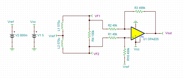
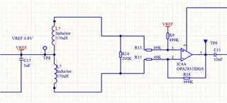
The circuit is equal to the one in the picture below. We have a dua coil Inductor, with a reference voltage of 0.8VDC, the coils of the inductor will be stimulated by a magnetic field. The capture signal at the output of the inductor is 1mV, over the 0.8VDC.

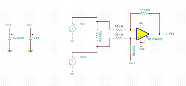
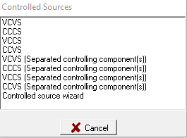
As I don’t know how to simulate it as it is, I used the circuit below, but I saw in one post the usage of VCVS to dp something similar.

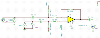
VG4 and VG3 respectively.


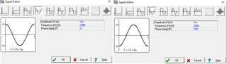
Both with DC level equals to 0.

There is way to simulate the circuit closely to the real usage, with the dual inductor?

  • Hi Gilson,

    If I understand what you are trying to simulate correctly, I think there are two ways you can go about simulating your circuit.

    The first would be to use voltage generator sources, similar to what you have above. This is probably the simplest method and would work well if the voltage sources are able to capture the behavior of the output of the inductors accurately.

    Here the voltage sources have the following settings:

    The second way to simulate the circuit would be to make use of the inductor models in TINA-TI, as shown below

    There are linear and nonlinear inductor models to choose from. You can adjust the properties of the models to match the inductors you are using which should help provide you and accurate simulation.

    Please let me know if you have any other questions.

    Thanks,

    Nick

  • Hi Nick, thank your for answering so fast. 

    About de second example, there is a way to simulate the frequency of 200kHz in the inductor?

    Another question, did you have a document that explain how the Controlled Sources of TINA works? 

    at:

  • Hi Gilson,

    In order to understand how best to simulate the inductor in your application, I have a few questions so that I can understand what your goal is. 

    1. You say that you are stimulating the inductors with a magnetic field, do you know what current is being induced by the magnetic field you are stimulating the inductors with?

    2. Are the inductors starting with an initial current flowing through them from the reference voltage source?

    3. Is the output of each inductor 0.8VDC +/- 1mVAC with the output being 180 degrees out of phase with each other?

    4. Are you able to elaborate on the application for this circuit? I can try to provide some reference designs that will have simulations if you can.

    Also, can you share what post you saw that used a VCVS to simulate an inductor? I am not sure that it makes the most sense to use a VCVS for this application, but knowing that post would help gain some context as to what you are trying to achieve.

    Additionally, I am working on trying to locate any documents about controlled sources to provide more information on those.

    Thanks,

    Nick