This thread has been locked.

If you have a related question, please click the "Ask a related question" button in the top right corner. The newly created question will be automatically linked to this question.

TL3472: TINA Simulation Result Is Confusing

Part Number: TL3472
Other Parts Discussed in Thread: TLE2142, NE5534, TLV9362, TLV9162, TLV9062

Hi,

This is a cost-sensitive PLC application, and TL3472 is the only part shown by our selection rules applied  to TI's 776, it has the lowest price with large stock in TI, In to V- rail-to-rail, and 3+ GBW. The application input voltage would be under 12V and we specifically need an op amp which has a good performance on input signal with 0.5V. We donot very much care about the performance on input signals above 4V or below 0.25V though it would be a gift if it also has a good performance on signals below 0.25V or even less with that price (we know there are many out there from TI, but they are too expensive).

From the datasheet, it looks like TL3472 would be a very good choice.

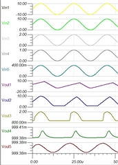
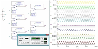
However, when we tried to import its PSpice model into TINA, we found the model is too simple with 30+ lines of code in it that made us up and down, and the TINA simulation result let us completely down:

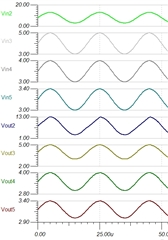
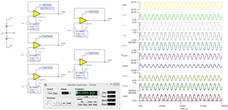
We managed to find a similar product from TI with rail-to-rail property of In to V- which is the same as TL3472 , it's TLE214x. The simulation result with TLE214x is good enough for our application but it's much more expensive and much less stock in TI:

The following is the parameter comparison between the 2 parts:

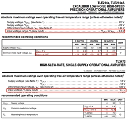
We can't see significant difference from the comparison above. Did we miss anything important? Why the simulations on the 2 parts differs that much?

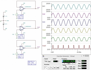
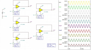
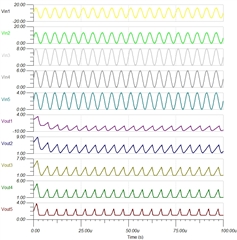
We did another set of test on TL3472:

Please see the attached TSC files.5460.TL3472.TSCTLE214x.TSC

Regards

Chao

  • Hey Chao,

    The answer can be seen with the Vout5 (200kHz with 200mV of amplitude). Your limit is not your bandwidth of your amplifier, but rather your slew rate. This is why you are not seeing the output attenuate like a bandwidth limit.

    The formula for slew rate of a sinusoid is 2*pi*f*V, where f is the frequency and V is the amplitude of the signal. This gives you a slew rate in V/s, you can divide by 1e6 to get to V/usec.

    TLE2142 has a much higher slew rate than the TL3472, which is why you do not see the output distorted. Please note that this device has slew boost, which may display different slew rate for different input voltages. In the model, you will see the datasheet typical slew rate, as the slew rate vs Vid is not characterized in the model.

    Best,
    Jerry

  • Hi Jerry,

    Thanks for the comments. I agree that the limit is not the bandwidth of TL3472, I passed the simulation on a part with GBW of 3MHz.

    However, the distortion is possibly caused by some other reasons rather than slew rate. According to the formula you provided, for f = 200KHz, Vin = 10V,  slew rate = 2*pi*f*V/ 1e6 = 12.6V/us, and the slew rate of TL3472 is 13V/us, this means for input signal below 10V the TL3472 should work properly, at least for Vin3 that is within 0-2V range, but it didn't. I changed all signal frequencies from  200KHz to 50KHz, and changed then amplitudes of Vin1 and Vin2 so that Vin1 needs slew rate of 6.3V/us, and 3.15V/us for Vin2. The following is the simulation result:

    Furthermore, I did a simulation on NE5534 (GBW=10MHz SR=9V/us):

    For Vin1 and Vin2, they need SR of 37.8V/us and 18.9V/us, but the SR of NE5534 is only 9v/us and it works fine.

    There must be something wrong somewhere else, for example, the PSpice model ?

    Best,

    Chao

  • Hey Chao,

    Does increasing the DC offset of the voltage help your simulation? It looks like you are hitting the rails. Additionally the TL3472 has a faster negative slew rate than positive slew rate. This is why when you are slew limited the output goes towards the negative rail?

    Additionally the TLE2142 is a more modern op amp macromodel architecture than the TL3472 and NE5534, so there may be some characteristics that are not modeled as accurately.

    Are your main concerns speed and cost? TLV9162/TLV9362 have good performance but have a bit higher quiescent current. These are on a 300mm process so they will have good supply.

    Best,
    Jerry

  • Hi Jerry,

    It does help a lot in simulation when add 3V more offset for Vin2 to Vin5:

    But this means we have to add DC offset to the application's input (0 ~ 12V, 88KHz). I really doubt about the completeness of the modelling of TL3472. Look at the simulation result from TLV9062 (SR=6.5V/us, GBW=10MHz, Rail to rail of In/Out):

    It looks fine to me even if 50mv is truncated at the bottom of the Vout3, Vout4, Vout5. The only issue for the use of TLV9062 in the application is the max input voltage is 12V, but the max V+ of TLV9062 is +5v. The application extracts the rising edge of the input signal, therefore it needs small signal to be identified to extend the PLC communication distance, our target is 0.5V. The  TLV9162/TLV9362 cost much more than TL3472 or even TLV9062. Now I am not sure whether the simulation result from TL3472 represents its real life behaviour.

    Best,

    Chao

  • Hey Chao,

    The TLV9162 is a 16V device.

    I agree, there may be differences in the models for the older devices, potentially the model reaches an undesired state at the edge of the linear operating range.

    Best,
    Jerry