Hi Team,
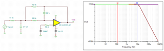
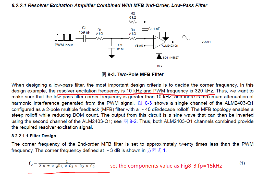
1) Based on P17 Figure 8-3 MFB component parameters and Equation 1 in datasheet, the filter cutoff frequency FP ≈ 15 kHz is calculated. Is the cutoff frequency set to be a bit larger than 10kHz and smaller than 1/5 to 1/10 of the PWM input frequency ok?
2)
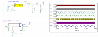
a. The frequency of the resolver is 10 kHz, why is the PWM frequency set to 320 kHz?
b. Why is the PWM input not set to the same operating frequency as the resolver?
c. Are there any specific requirements for setting the PWM frequency?
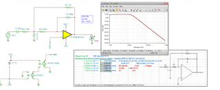
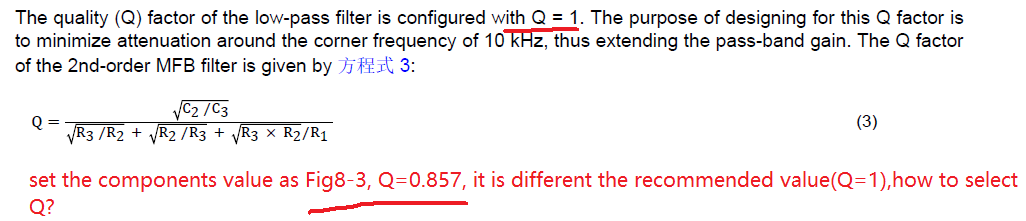
3) Based on the spec, it is recommended to set Q=1, but based on P17 Figure 8-3 MFB component parameters and Equation 3 of Q values in datasheet, Q=0.857 is calculated. The recommended value is different from the actual calculated value. So is the Q value selected to be =1 or <1? If < 1 or > 1, what would be the appropriate value?
Could you help check this case? Thanks.
Best Regards,
Cherry