This thread has been locked.

If you have a related question, please click the "Ask a related question" button in the top right corner. The newly created question will be automatically linked to this question.

OPA182: Advice on low current measurement of high voltage system

Part Number: OPA182
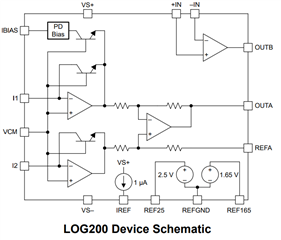
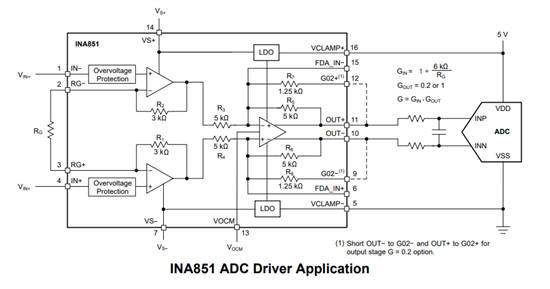
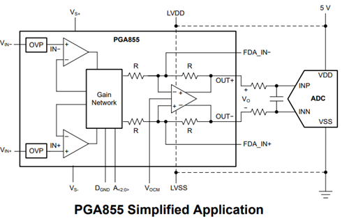
Other Parts Discussed in Thread: OPA206, OPA192, OPA3S328, LOG200, LOG114, OPA2206, INA592, INA849, INA851, PGA855

Hello,

I'm looking for advice on how you smart folks would measure small currents but also a wide range of current in a high voltage system.

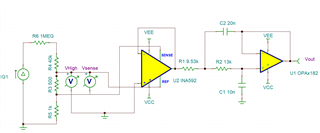
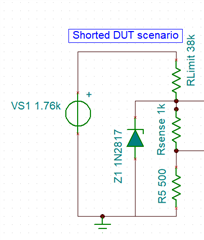
Details: I am building an instrument to measure low currents, down in the 10's of nA range, all the way up to about 1mA (I want to implement a ranging function in future rev but for now assume fixed gain). We are measuring leakage current of high voltage mosfets and apply as much as about 2kV to the drain of the mosfet and have current limiting resistor on the low side and a shunt resistor to make a voltage divider for calculation of current, as shown in figure below. The output must be single ended (unfortunately) 0-5V. 

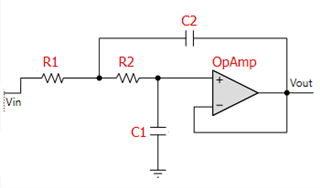
Right now I am using OPA182 as a precision buffer (fig. 2) but am wanting to also include a low pass filter to help especially with measurements in the lowest current range. I am thinking of a 2nd order butterworth filter, sallen key topology (easily created with TI's filter pro tool) because it is a simple circuit with only a few extra passive components. Would you folks recommend buffering first, then filtering? Or is it safe to buffer and filter together in one stage? Is it overkill to use such a precision op amp if I have the ability to cancel the offset digitally?

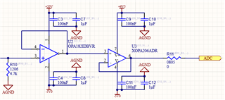
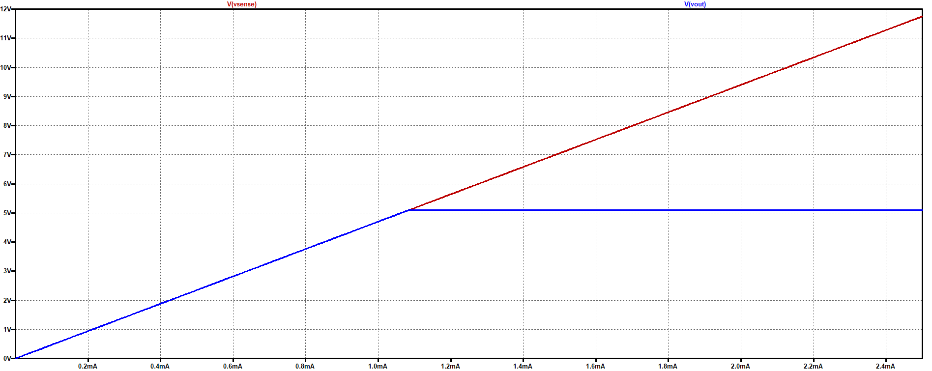
I am also interested in people's opinions on output voltage limiting. In my current solution (fig.3), I have used another precision opamp, OPA206 which has protection on its inputs to safely limit the output to its rails. However this is probably a non-ideal solution as well as expensive. Should I just go back to the tried and true zener on the output of a buffer/filter? The microcontroller doing the measurement also controls a high voltage relay that will disconnect the circuit in the case of over-current, but it is not very fast due to me multiplexing 14 channels and having a pretty low sampling rate. Again for this I want to implement a fast analog disable but for now I am sticking with digital control. So I am thinking of using a zener that will protect the microcontroller but allow the ADC to read its full measurement range, and rely on the microcontroller to disable the circuit in about 500ms.

What do you think? Thanks in advance for any input.

fig.1 Voltage divider

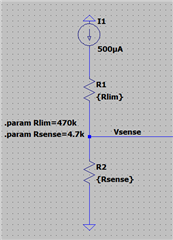
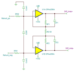
fig.2 shunt monitor buffer 

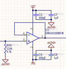
fig.3 double buffered current monitor and voltage limiting

  • Hi Henry,

    You may consider using a single precision amplifier to perform both the Sallen-Key low-pass filter function/buffer on a single stage amplifier.  The Sallen-Key offers high-input impedance.  If you want to measure currents to the 10nA precision, you could consider using a precision CMOS linear op-amp device such as the OPA192 which has very low input bias current in the ±5pA typical, low offset and low-drift.

    If you are interested in the accurate measurement to 5V full-scale, and do not care for op-amp outputs above 5V, you could power the buffer/filter amplifier with +6.5V and -5V supplies. The Sallen-key filter configuration uses  resistors at the non-inverting amplifier input.  If the RSENSE voltage during a fault will reach +12V, you could design the filter and scale the input resistor components so the series resistance protects the op-amp non-inverting input limiting the input current during the fault where RSENSE reaches 12V.

    Please note, in the case of  using the OPA192, the output of the op-amp during a fault is only limited by the op-amp supplies.  If the op-amp is powered with bipolar supplies +6.5V and -5V, and your ADC can only withstand unipolar voltages from 0V to 5V, you will still need a clamp at the op-amp output to protect the ADC for negative voltages and voltages above 5.3V during fault conditions.

    Thank you and Regards,

    Luis

  • HI Henry,

    As alternate solutions, you could consider using a programmable gain transimpedance  amplifier or a Logarithmic amplifier solution.

    Since the application requires to measure a wide range of current, from 10nA to 1mA., and if the application requires a high-precision current measurement down to 10nA,  you could consider using a transimpedance amplifier with programmable gains.  Below is an application note to implement a programmable gain transimpedance amplifier using the OPA3S328.  The OPA3S328 incorporate the analog switches to easily implement the programmable gain TIA.

    High-speed (40 MHz) high-precision (60 µV) low-noise op amp with integrated gain switches

    OPA3S328EVM — OPA3S328 evaluation module for high-speed (40 MHz) high-precision (60 µV) low-noise op amp

    Build a Programmable Gain Transimpedance Amplifiers Using the OPA3S328

    Logarithmic Amplifiers:

    We also offer logarithmic amplifier solutions.  The Logarithmic amplifier spans across multiple decades of current with good resolution without the crossover region/uncertainty associated with a switched gain amplifier

    Logarithmic vs Non-logarithmic Output Reading

    For example, the LOG200 is our newest log amp, this is a fast, high-precision logarithmic amplifier and features a 120 kHz bandwidth at 1nA of input current, ±1% gain error, and ultra-fast response times. With a rise time of 0.22μs and a fall time of 0.63μs to a 10-100nA step, the LOG200 will be able to quickly detect changes in optical power across many decades of current. The LOG200 has built off its predecessor, the LOG114, and has improved on key specifications.

    High-speed precision logarithmic amplifier with photodiode bias and dark-current correction

    LOG200EVM — LOG200 evaluation module for high-speed precision logarithmic amplifier with photodiode bias


    Device

    Input Current Range

    Log Conformity Error

    Gain Error

    (25°C)

    Step Response 10nA-100mA

    (µs)

    BW at 1nA

    (kHz)

    Temperature Range (°C)

    Package Options

    LOG114 

    100pA – 10mA

    0.2% (1nA-100A)

    ±2.5%

    1.5

    5

    -5 to 75 °C

    4x4mm 16 QFN

    LOG200 

    100pA – 10mA

    ±0.2% (10nA–100A)

    ±0.5% (10nA–1mA)

    ±0.75% (1nA–10mA) 

    ±1% 

    0.22 rising

    0.63 falling 

    120

    -40 to 125 °C

    3x3mm 16 QFN

    Thank you and Best Regards.

    Luis

  • Hello Luis,

    Thanks for the feedback and suggestions. I'm definitely interested in both of those approaches (the amp with integrated switches or log amp) as a possible solution.

    But I want to ask your opinion of an idea I have to achieve the best precision I can. I am thinking of using a difference amp across a sense resistor with a gain of 1 or 2, or possibly higher (depending on sense resistor used). Followed by the LPF discussed already. For example as shown in fig.1 below. I should mention I was recently made aware of a requirement that is forcing me to use a smaller limiting resistor, it will probably be between 30 and 40k. And due to the high voltage of the system I need to also keep the sense resistor relatively low so that the ratio does not produce excessively high voltage at the sense node. So I'm looking at using probably between 500 and 1k ohm for the sense resistor.

    And about the difference amp and sense resistor, I am thinking it would be best to "elevate" it above ground by putting it in series with another resistor. Is this a valid technique to reduce common mode noise? Is the input impedance to the sensing circuit drastically reduced due to the internal resistors of the difference amp (fig.2)? Is this necessarily a bad thing?

    fig.1 Difference amp + LPF

    fig.2 Diff amp pinout

    Thanks!

  • HI Henry,

    I need to ask a couple of questions:

    - What is the DC accuracy and required on your measurement, (in nanoamps or microamps)?

    - What is the resolution (in uARMS ) required on your measurement, (in nanoamps or microamps)?

    - What is the ADC bit resolution connected at the output of the amplifier circuit?

    - What is the ADC reference voltage or ADC full-scale range?

    A TIA has the advantage of offering a relatively low impedance input, where the TIA offers a virtual short, and allows you to convert the current to voltage independently. The TIA gain is set by the feedback resistor independently.

    Similarly, the logarithmic amplifier can also offer relatively low input impedance.

    A difference amplifier or instrumentation amplifier measuring the voltage across the shunt can certainly work, BUT, my primary concern with the difference amplifier and/or buffer/filter circuits above, is that the original post you have mentioned that you require to measure a low currents in the 10nA range, and this is a very small voltage across the shunt resistor, the 500 Ω*10nA = 500nV across the shunt which will be very sensitive to noise, and intrinsic errors of even a very low noise, high precision amplifier; unless we increase the resistor or you have a more relaxed accuracy at the lowest current measurments.

    The questions above will help us look into the different possibilities,  

    Thank you and Regards,

    Luis

  • Hi Luis, yes you're right I need to be more clear on my requirements. Especially with my assertion of needing to use a smaller sense resistor, the accuracy at the low current range is going to suffer.

    1) DC accuracy - In the nanoAmp range, it is not as important, but would like to have confidence that I'm "in the ballpark" when the system is reporting below 1uA. Above 1uA I need to be pretty accurate. I.e., I'd like to be within 5% of reality for current > 1uA. Below 1uA, 10-20% accuracy is probably good enough.

    2) Resolution - the old version of this system reports current in 10's of nanoAmps. I could probably relax this to multiples of 50nA or maybe 100nA with the smaller sense resistor.

    3/4) I'm using a 20-bit ADC and sampling pretty slow, about 180 times/second. I have some flexibility on the voltage reference/full scale range. The microcontroller I'm using (PSoC 5LP series) has a pretty good 0.1% internal reference of 1.024V. I can use 1X, 2X or 6X the vref as the range. Or I can use VDD as the full scale range, although less accurate. I could also provide my own Vref in the range of 0.9 - 1.3V. I'm considering moving to say 1.25V to use 0-2.5V range for this system with smaller sense resistor. Although actually 0 - 2.048V would be fine too if I want to measure up to 2mA with a 1K sense resistor. For that range I would have a resolution of about 1.95uV per div. 

    The other factor that is complicating my design choices is protection. I mentioned in the beginning that this is part of a high voltage system. And I need to protect the measurement circuit from the case of a short circuit at the DUT. See schematic below. Due to the constraint I mentioned in previous post (I can go into detail about this if you want, but take it for granted for now), I am going to limit the total resistance of the current limiting resistor + sense resistor to <40k Ohms. This system could use Voltage as high as 1760VDC. So if the DUT were to short and we have a voltage divider consisting of for example, 38k and 1.5k as shown, the voltage at the sense node would be 67V. It is for this reason I am considering using a diff amp supplied by about 20V on the high end that can tolerate voltage beyond its supplies. However, it is seeming more practical now to use an op amp and protect its input with a zener around 17 or 18V. I just have to be careful with part choice to find a zener that is not very leaky at lower voltages in the measurement range, and also can handle the power dissipation. From there I then will still need protection at the output to protect the ADC. This could be accomplished by another ~5V zener or maybe relying on a specialty op amp that has input overvoltage protection. I should also note that I have a high voltage relay that will be opened in the case of over-current (or current exceeding the measurement range) but it is not very fast to disable. But it should be <1s so the zener and limit resistor must handle some power but it should never be for long continuous periods of time.

    fig.1 Shorted DUT and abs max high voltage input

    Hopefully this provides more context for you and narrows the design requirements. Thanks for all your feedback and I look forward to hearing your opinion! And of course let me know if you have more questions on the requirements.

    -Henry

  • Hi Henry,

    Below a couple of ideas:

    The INA592 difference amplifier configured on G=2 has a differential input impedance of 6kΩ + 6kΩ = 12kΩ.  Since the sense resistor is 1kΩ and relatively large compared to the 12kΩ input impedance of the instrumentation amplifier, there will be an error of approximately ~7.8% on your current measurement across all current ranges.  One simple solution is to buffer the inputs of the INA592 with the OPA2206 dual op-amp.  The OPA2206 has overvoltage protection to ±40V beyond the op-amp supply rails, low noise and relatively low input bias current (less than 1nA).  We could set up the OPA2206 as simple buffers or in a gain configuration and follow the OPA2206 stage with a difference amplifier. 

    Another option is the INA849, and placing 10k series resistors at the instrumentation amplifier inputs.  The 10kΩ series resistor at the inputs of the instrumentation amplifier will limit the current into the input pins of the INA to less than ~10mA during the 67V fault.  Since you are sampling at slow sampling rates, the thermal noise contribution of the series resistor is small.  The INA849 offers very good DC precision, low drift, relatively low noise (ultra low noise at high-gains) and high-input impedance. 

    If your 20-Bit ADC accepts fully-differential inputs:

    If your 20-Bit ADC accepts fully-differential inputs, you could use the INA851 fully-differential output instrumentation amplifier.  The INA851 offers overvoltage protection up up to ±40V above the device supplies during the default condition.  The Gain of the device can be set with a single RG resistor.  The INA851 input stage can be powered with a +30V and -5V supplies.  The INA851 output stage feature built-in clamping circuitry to protect the ADC or downstream device against overdrive damage.  Essentially, you would connect the Vclamp+ and Vclamp- pins to the ADC supplies. The INA851 input stage offers very low noise, specially if you set the input stage on a gain. Input bias current is ~5nA typical (18nA max across temperature).

    See below:

    The PGA855 is  programmable gain amplifier, also a fully-differential output device, with overvoltage input protection up to ±40V beyond/above the device supplies. The input stage can be powered with the the +30V and -5V supplies. The output stage has a separate set of supplies and can be powered with the ADC supplies. The device offers programmable binary gains from attenuation,  0.128x, 0.250x to gain of 16x controlled.  This device will be very flexible allowing different ranges of current by adjusting gain, very low noise and low input bias current.  


    Nevertheless, the PGA855 or INA851devices are primarily intended for fully-differential input ADCs.  Let me know if I should focus on single-ended or fully-differential ADC input.  It is also possible to use the PGA855 and INA855 and follow with a difference amplifier to perform the differential to single-ended output conversion.

    Thank you,

    Best Regards,

    Luis

  • Hello Luis, yes your explanation about the difference amplifier is what I was getting at about the input impedance, so for this situation maybe it is not the best option to connect directly to the sensing resistor. 

    With your suggestion on the OPA2206, are you saying to configure it how the block diagrams of the INA851 is shown, to buffer both sides of a sense resistor then use difference amplifier? On this topic, do you think I will truly see much better performance (i.e., noise immunity) using a method like this or instrumentation amp? Or could I justify sticking with single ended input with precision amp, to single ended output?

    I really like the INA849 but it sure is expensive... 

    I also really wish I could use differential ADC, however I am essentially out of GPIOs to use. I'm considering freeing some up using an I/O expander but with the other features of this project seemingly ever expanding instead of retracting, I'm looking at needing those pins for other functions. I could maybe find a way around this if I could justify the performance advantage. Do you have any resources/links that talk about this that might convince me to make differential happen "at all costs"?

    I think for now my take is that I almost definitely must stick with single ended ADC, but am on the fence about making a differential measurement at the sense node. Right now I'm heavily considering keeping it simple, and buffering/filtering the shunt resistor, and using a zener that is well outside the normal measurement range to protect the input, hopefully without introducing any error in the measurement range. Then clamp the output with a 5V zener to protect the ADC/microcontroller. 

    Thanks as always for your thoughts,

    -Henry

  • Hi Henry,

    One can certainly achieve high-precision performance with a single-ended output solution. The fully-differential option was presented above since incorporate the clamps and other functions that may have been of interest for the case the ADC offered fully-differential inputs. That said, the majority of instrumentation amplifiers are single-ended output, and are well know to achieve a very high level of performance in high-accuracy, low-noise systems as well.

    Yes, you can certainly configure the OPA2206 with 3 precision, low drift resistors in a differential configuration allowing you flexibility to set them in a gain configuration. If you decide to use a gain of 1-V/V, you can simply replace RF1 / RF2 with 0-ohms, and leave RG unpopulated.

    Let us know if you have a schematic you wish as to review.

    Thank you,

    Cheers,

    Luis